


320 Slice CT Scanner Slip Ring: Technology Requirements and Solutions
BY NBG
 2026-09-15
VIEWS: 1528

320-Slice CT Scanner Slip Ring: Technology Requirements and Solutions
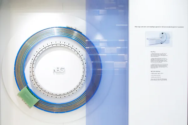
The 320-slice CT slip ring is the part you don't see, but it's necessary for whole-organ, single-rotation imaging. Wide-detector CT scanners can acquire an image of the whole heart or brain in a single pass, but they must transmit a large volume of image data from a moving platform to a stationary computer without loss. This article shows what a 320-slice machine needs from its slip ring and how modern engineering can provide it.
What Is a 320-Slice CT Scanner?
A CT scanner makes cross-sectional images by rotating an X-ray tube and detector array around a person. Along the z-axis, which runs parallel to the patient's body, 320 detector rows capture data. This is what "320 slices" means. The detector covers a large tissue area in a single rotation because 320 rows operate simultaneously. This is faster than building it up helically over many table advances.
The best reference tool in this group is the Canon Aquilion ONE family. The Aquilion ONE 320 can rotate once and cover 8 cm of anatomy. Newer versions of the platform have 640 detector rows that can cover 16 cm in the z-axis. On the base platform, the rotation speed is 0.35 seconds per turn. On the Aquilion ONE INSIGHT Edition, that speed increases to 0.24 seconds, which imposes significant centrifugal forces on all the moving parts inside the gantry.
There is a big clinical return. A cardiologist can stop-motion a beating heart in its tracks in one turn. Neurologists can assess blood flow to the brain without requiring several passes. But engineering tension matters just as much. When you combine more detector rows with faster rotation, you get an exponentially larger amount of image data that must pass through the rotating interface each second.
Why do slice count and rotation speed drive slip ring design?
Each extra detection row adds its own stream of digital data. Each increase in rotation speed reduces the time available to send the info. The slip ring between the moving gantry and the stationary frame has to change size with both at the same time. This is what makes the engineering problem for 320-slice systems so different from those for lower-count systems.
The Data Transmission Challenge
During a scan, the X-ray tube and detector array keep moving around the body. You can't send power and data to and from the gantry with fixed cables because they would break if they were constantly turned. The slip ring solves this problem: it sends kilowatts of electricity to the spinning gantry and streams the detector's image data off it across a moving boundary without stopping.
This problem has grown with each new wave of scanners. Older contact slip rings could handle data rates of 20 to 800 Megabits per second, which was fast enough for thinner detector arrays that produced less data. In a 320-slice system, the detector array creates gigabytes of data, every second, which is too fast for sliding metal-on-metal contacts to handle consistently.
Contact-resistance noise is the main problem with contact-based data transfer at these speeds. Tiny changes in the electrical connection between the brush and ring cause signal errors that mess up the fast digital stream. Over time, mechanical wear worsens this, gradually reducing performance.
Because of this, 320-slice CT devices require signal channels to move away from contact-based data transfer. To understand how that change happens, look at the four things that make up a modern CT slip ring.
CT Slip Ring Requirements
A 320-slice slip ring must meet four requirements simultaneously: handle large amounts of raw data, protect the signals, be mechanically robust, and remain reliable over time.
20 Gbps+ Data Transmission
The main requirement is to transmit image data from the detector array at 20 Gigabits per second or higher without errors. To get this number, multiply the number of detector rows by the rotation rate, the bit depth of each measurement, and the number of views recorded per rotation. As new product generations emerge with more of these variables, the required data rate increases.
Low Latency and Bit-Error Integrity
"Low latency" isn't really a good way to describe what matters in CT data transfer for people who work in tech. What's really needed is a low, reliable bit-error rate and steady, predictable throughput. A bad view or a late data packet doesn't just make a small part of the image less sharp; it can also introduce reconstruction flaws that make the whole image less reliable for diagnosis.
Contact-based channels can experience short-term increases in contact resistance when brushes move over any rough spots on the ring's surface. These spikes lead to burst errors that are hard to fix and can't be eliminated by adding more copies of the data. Contactless channels eliminate this failure mode by avoiding any physical contact. This makes the signal path across the rotating gap cleaner and more reliable.
High-Speed Rotation and Mechanical Loading
CT gantries that can turn in less than 0.3 seconds operate at around 200 to 280 RPM on rings close to 1 meter in diameter. Centrifugal forces work on every part that is attached to the rotating frame at those speeds. The slip ring must maintain power and signal integrity while it is continuously spinning at high speeds and vibrating, without the rotating and stationary parts moving out of alignment.
Because of the large bore required for patient access (typically 78 cm in diameter), the slip ring must have a correspondingly large diameter. This increases the centrifugal loads on the rotating assembly. This must be considered in both the material and structural stages of mechanical design to ensure limits remain stable over years of high-speed operation.
High Reliability and Low Maintenance
An IA CT scanner in a busy radiology department can work for over a thousand hours a year. Clinical uptime is essential; unplanned maintenance directly affects when patients can be seen and how much money the hospital makes. The slip ring must be designed to operate continuously for a certain number of years with only a few maintenance windows.
Contactless data channels directly help this goal. Because there is no direct contact, there is no wear surface, brush material, or ring surface to resurface. Power channels still require sliding contacts, but new fiber-brush technology significantly extends repair intervals. Fiber-brush power contacts can withstand hundreds of millions of rotations, so they require far less maintenance than carbon-brush designs.
Engineering Solutions
To meet these four needs, the industry separates data and power onto different transport physics within a single ring assembly. Power moves through the rotating interface via long-lasting sliding contacts. In contrast, image data moves through contactless pathways unaffected by the wear and tear that affects contact performance.
Optical Data Channels
In an optical transfer architecture, the detector's digital output is converted into modulated light, which is then transmitted across the rotating gap via lenses or fiber bundles. Optical channels have a very wide bandwidth and are very resistant to electromagnetic interference. This is a big plus in a CT gantry, which has a lot of electromagnetic activity. The real issues are dust, which can degrade the optical path, and the optoelectronic conversion hardware at both ends of the link, which complicates matters.
Capacitive / Near-Field Contactless Coupling
For capacitive coupling, the transmitter and receiver antennas are placed around the ring. Digital data changes the electric field that passes through the small gap between the two structures. This allows a large amount of data to be transmitted quickly without physical contact or wear mechanisms. Leading makers' near-field capacitive designs can handle up to 25 Gbps per channel, making them ideal for the large volumes of data produced by wide-detector and photon-counting CT systems. For the fastest aggregate data rates on the market, this is now the design of choice.
Integrated Power + Data Architecture
In real life, both technologies work together in a single small ring assembly. The X-ray tube requires several kilowatts of power, which is supplied via fiber-brush sliding contacts. All image data is sent through contactless optical or capacitive pathways.
Looking Ahead
Photon-counting CT detectors, now used in hospitals, produce even more data per rotation than conventional energy-integrating detectors. Add the industry push for faster spinning speeds, and the total data that must be sent reaches hundreds of gigabits per second. To keep pace, future slip ring designs will likely move toward fully contactless systems with higher per-channel rates.
Conclusion
Whole-organ imaging in a single rotation is what makes a 320-slice CT scanner clinically useful. A slip ring inside the gantry makes this possible, and it is invisible. That ring must move at least 20 Gbps of error-free image data off a fast-spinning frame while also delivering kilowatts of power.
It has to do all of this while dealing with real centrifugal loads and years of constant clinical use. Today, this is possible thanks to contactless optical and capacitive data channels. Tomorrow, the next wave of photon-counting and ultra-fast CT systems will also be possible thanks to these technologies. OEM experts evaluating slip ring partners for next-generation CT platforms should place greater weight on vendors that have demonstrated they can deliver contactless channels with the throughput rates their detector architectures require.
NBG Innovations Group Pte.Ltd.
#13-13A, International Plaza, 10 Anson Road, Singapore (079903)


Navigation
 HomeSustainable
Product