


Electrical Isolation Techniques in Slip Rings
BY NBG
 2026-06-29
VIEWS: 500

Electrical Isolation Techniques in Slip Rings
Electrical isolation is one of the most critical engineering challenges in slip ring design. A slip ring has to transmit power, signals, or data across a rotating interface, which makes it more prone to problems than fixed connectors. A basic slip ring and a high-reliability assembly are often different because of how well their isolation methods are designed and assembled.
Why Electrical Isolation Matters in Rotating Systems
The Rotating Interface Problem
It is hard to find the stationary to rotor boundary because it makes shared ground paths, parasitic capacitance between adjacent rings, and brush contact noise that can leak into nearby signal channels. When stationary and rotating grounds share conductive paths through the housing or shaft structure, ground loops are also more likely to happen.
Failure Modes Without Adequate Isolation
Dielectric breakdown between high-voltage power rings and low-level sensor channels. Cross-channel interference that makes analog signals less accurate and increases digital bit-error rates. Leakage current that can be dangerous in medical, CT, MRI, and other systems that connect to patients according to IEC 60601-1. Over time, the buildup of conductive brush dust can cause a gradual loss of insulation resistance.
Solid Insulation: Dielectric Materials and Structural Design
Dielectric Material Selection
The choice of material is what makes solid isolation work. PTFE is still the best insulator for precision slip rings because it has a low dielectric constant of about 2.1, a dielectric strength of more than 30 kV/mm in virgin grades, and it is very resistant to chemical contamination from brush debris and lubricants. Because it doesn't stick, it also helps stop conductive dust from tracking on the surface.
When operating conditions require more than standard PTFE can offer, other materials are used. People often use glass-reinforced epoxy, such as G-10 or FR4, in structural insulating parts. PEEK works well in high temperature environments, and ceramic-filled composites are often used in very high voltage situations. In every case, designers should pay attention to the volume resistivity, dissipation factor, thermal stability, and how the surface behaves when it is dirty. A volume resistivity of more than 10² ohm-centimeters is a good standard for many high-reliability designs.
Insulation Resistance and Dielectric Strength Testing
Insulation resistance (IR) is measured at 100 V, 250 V, or 500 V DC between circuits and housing. The goal is usually to achieve values≥500 MΩ at room temperature. Hi-pot (dielectric withstand) testing checks the breakdown voltage margin. According to ASTM D-149 / IEC 60243-1, the weakest air-gap point (usually ~3 kV/mm in air at standard conditions) determines the design margins.
Galvanic Isolation: Breaking the Ground Path Entirely
Optical (Opto Electronic) Isolation
Optical isolation uses an LED and a photodetector to send signals across a barrier, preventing direct electrical connection between circuits that are not moving and those that are. Optical isolation is a good choice for analog channels in high-voltage assemblies where the bandwidth needs are less than 1 MHz.
Its trade-offs are just as important. LED switching speed limits data rates; power loss is usually higher than with other isolation methods; and light output can degrade over time, requiring long-life systems to be recalibrated.
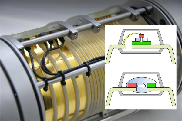
Inductive (Transformer Based) Isolation
Inductive isolation uses two coils that are magnetically linked and separated by a barrier that keeps them from touching. A changing magnetic field moves energy or data from the stator to the rotor, where it is reassembled. This method provides galvanic isolation without any physical contact, making it easy to transfer moderate amounts of power and do many digital communication tasks.
It is widely used in contactless slip rings, such as those found in wind turbine pitch systems and high-speed packaging machines. The fact that it is sensitive to external magnetic fields is its biggest problem, so electromagnetic design and shielding must be carefully considered.
Capacitive Isolation
Capacitive isolation sends signals through a small gap by coupling them with an electric field. It works well for high-speed data channels because it lets AC through and blocks DC. It can even have more bandwidth than optical isolation. It also has a long life and is very resistant to magnetic noise.
The main problem is that it can be affected by electric fields from nearby high-voltage conductors, and it isn't usually the best choice for transferring more power. Because of this, hybrid contactless slip ring designs often use both capacitive and inductive power transfer together.
Channel to Channel Isolation Architecture
Physical Channel Separation and Ring Layout
Layout is the first step to good isolation. You shouldn't just mix power and signal rings; they should be kept apart to meet the clearance requirements. A good rule of thumb for multi-channel slip rings is to put power channels at one end and signal channels at the other, with dedicated ground rings between the two groups where needed.
The material of the contact is also important. Gold and platinum contacts are better for signal channels because they don't form oxides, exhibit lower resistance variation, and help maintain a strong signal at the rotating interface.
Electromagnetic Shielding Between Channels
When several channels are close together, just spacing them out isn't usually enough. Grounded conductive shields, usually made of copper or aluminum, can be placed between ring groups to reduce both capacitive and inductive coupling. In RF slip rings used in radar or pan-tilt systems, inter-channel isolation often needs to exceed 60 dB. It needs both structural separation and special shielding.
It is also important that the ground plane stays connected. Any hole or break in a shield or ground path can act like a slot antenna, radiating EMI. For high-speed channels, it is very important to keep a low-impedance shielding structure that is always there.
Differential Signaling for Noise Rejection
Differential signaling adds another level of security. Standards like RS-422, RS-485, CAN bus, and Ethernet use paired conductors to reject common-mode noise, since interference usually affects both conductors equally. The receiver only looks at the voltage difference between the two.
This method works best in places with long cable runs or heavy EMI. It also makes the mechanical slip ring layout easier by allowing channels to tolerate residual crosstalk in dense assemblies.
Application Specific Isolation Requirements
Medical Imaging (CT Scanners / MRI)
Isolation is one of the hardest things for medical systems to do. IEC 60601-1 says that equipment used near patients must have very low leakage current and very high insulation resistance. In CT systems, slip rings can simultaneously carry high-power X-ray voltages and low-level control and detector signals. That makes it especially hard to keep these channel groups separate. In many cases, reinforced insulation is needed at critical edges.
Turbines for wind
Slip rings used in wind turbine pitch control systems must withstand AC voltages of 575 to 690 V, as well as switching transients and surges caused by lightning. In this environment, brush dust is always a problem, so designers often use open-air spacer layouts and non-stick insulating surfaces to reduce tracking currents. A ground ring near the active rings also helps keep bearings safe from shaft currents that could damage them.
Defense and radar systems
RF isolation is very important for radar and defense uses. To stop signal coupling, phased-array radar rotary joints often need inter-channel isolation of more than 60 dB across the entire operating band. To do this, RF paths are usually kept separate from DC power and control circuits in different parts of the structure. The housing has Faraday-style shielding built in.
Selecting the Right Isolation Strategy: A Decision Framework
Key Selection Parameters
PTFE insulation or optical isolation can improve the performance of low voltage signal channels. Medium voltage power channels rely more on creepage and clearance that are rated correctly. Above 1 kV, it becomes more important to have stronger insulation and longer creepage. For analog low-level signals, galvanic isolation is usually the best choice. For high speed digital channels, inductive or capacitive methods are usually better. IEC 60601-1 is for medical applications; IEC 60664-1 is for industrial systems; and alignment with IEC 61800-5-1 may be needed for motion-control or drive-related systems.
Common Design Errors to Avoid
Some common mistakes include failing to recognize the extent of pollution in brush heavy areas, mixing power and signal grounds in multi-channel layouts, and failing to account for bearing isolation in generator or turbine systems. These mistakes might not cause the system to fail right away, but they do cause reliability problems that get worse over time and are expensive to fix later.
Conclusion
Getting electrical isolation right is important for designing slip rings. That means selecting the right dielectric materials, setting appropriate creepage and clearance distances, using the right galvanic isolation method, and ensuring adequate shielding. Most of the time, that protection consists of PTFE and other insulating materials. Since modern slip rings are supposed to carry power, Ethernet, RF, and sensor signals all at once, isolation has become a key factor in long reliability. When putting together different types of channels, it's best to check the manufacturer's technical data, use the appropriate IEC standard, and involve application engineers early.
NBG Innovations Group Pte.Ltd.
#13-13A, International Plaza, 10 Anson Road, Singapore (079903)


Navigation
 HomeSustainable
Product

NBG
INVITATION