


How to Improve Reliability in Compact Slip Rings
BY NBG
 2026-06-10
VIEWS: 601

How to Improve Reliability in Compact Slip Rings
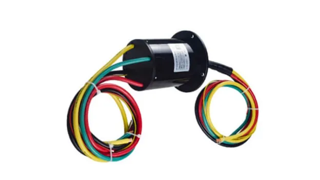
Compact slip rings allow power and signals to transfer between a rotating part and a fixed structure. Gimbals, UAVs, robotic joints, medical imaging systems, and pan-tilt surveillance units all use them. The engineering problem is that reducing the form factor worsens every reliability risk. Less physical space means more heat, less room for contact geometry, and less room for shielding. Reliability comes from picking the right materials, sealing the area, controlling signals, being exact with mechanics, and having a good maintenance plan.
Why Compact Slip Rings Present Unique Reliability Challenges
Miniaturization is not merely a reduction in size, but also an increase in risk density. The reliability challenge with compact slip rings lies in the fact that, to successfully implement them in engineering applications, it is essential to precisely understand the specific failure modes of components within confined spaces.
The Trade-Offs of Miniaturization
While the miniaturization of miniature slip rings enhances integration, it also introduces significant engineering trade-offs. The reduction in outer diameter directly limits the design flexibility regarding ring width, brush geometry, and contact pressure, thereby affecting the stability of contact resistance and wear life. Furthermore, the compact size leads to increased power density and thermal density, accelerating wear at the contact interface. Space constraints also severely limit cable routing and electromagnetic interference (EMI) shielding effectiveness, making signal integrity issues—which can be resolved through physical isolation in larger components—particularly prominent in miniaturized applications.
Primary Failure Modes in Small Slip Rings
There are predictable ways compact slip rings can fail. Most of the time, high or unstable contact resistance is caused by surface oxidation or worn contacts. When the brush-to-ring contact isn't consistent, electrical noise and signal dropout occur. It gets worse when the device vibrates or goes faster. Mechanical wear accelerates when misalignment or excessive brush spring force is present from the start. Moisture and dust can get inside sealed enclosures if the IP rating is too low for the environment where the device will be used. Over time, brush debris can accumulate inside these enclosures, making the contacts dirty.
Contact Material Selection for The Foundation of Electrical Reliability
Compared to other individual variables, the contact pairing between the brush and the slip ring has a decisive impact on contact resistance stability, background noise levels, and service life. Therefore, material selection must be based on a systematic evaluation of signal type, duty cycle, and operating environment to ensure optimal performance under specific operating conditions.
Precious Metal Contacts with Gold, Silver, and Their Alloys
For signal-grade compact slip rings, gold-on-gold contact systems are the best in the business. Gold doesn't form an oxide layer, which keeps transmission noise-free for tens of millions of revolutions. In their pure form, precious metals are too soft, so engineered alloys like Paliney 7, Paliney 25, and palladium-silver compositions combine hardness with corrosion resistance. Silver-graphite composites are a good choice for moderate-duty applications because they lubricate themselves and offer lower friction at a lower cost.
Plating Strategies for Cost-Optimized Designs
In commercial applications, hard gold plating on copper alloy rings is the most common cost-optimization strategy. In contrast, advanced tri-metal ENAP (electroless nickel-autocatalytic palladium) coatings exhibit corrosion resistance comparable to that of gold, along with higher surface hardness. Their contact resistance can be precisely controlled to within 0.001 Ω, while a surface roughness of Ra 0.2–0.4 µm effectively suppresses debris accumulation, thereby significantly extending maintenance intervals.
Table 1: Contact Material Comparison
Material | Best For |
Gold-gold contact pair | High-Frequency Data Communication |
Paliney 7 / 25 alloys | Mixed transmission, medium to high current |
Silver-graphite / Silver-plated | Power Transmission |
Hard gold plating (ENAP) | Cost-effective precision applications |
Carbon graphite | Ultra-high-power transmission |
Matching Brush and Guide Rail Materials
The compatibility between the materials of the brush and the slide rail directly determines the wear rate of the contact pair and the morphology of the wear debris. If there is a mismatch in the hardness of the paired materials, surface damage will be significantly exacerbated. Fiber brush technology employs a tangential bundle structure of precious metal fibers, which reduces contact normal force while ensuring excellent electrical conductivity; this solution has been validated in radar and helicopter de-icing systems with high cycle counts. For specific applications, carbon-graphite brushes are recommended for high-speed, high-current power channels, while precious metal monofilament brushes should be used for clean, low-noise signal channels.
EMI Shielding and Signal Integrity in a Miniaturized Form Factor
In miniaturized structures, compact enclosures make it difficult to effectively isolate noise sources from sensitive signal paths. Therefore, effective shielding depends not only on shielded cables but also on careful structural design.
Root Causes of Electrical Noise in Compact Assemblies
The root cause of electrical noise lies in microscopic arc discharges at the contact interface between the brushes and the slip rings; this phenomenon is significantly exacerbated under conditions of high-speed rotation or mechanical vibration. In high-density, multi-channel designs, electromagnetic coupling between adjacent channels can cause crosstalk. Furthermore, the compact layout shortens the interference path, making it extremely easy for noise to be introduced into unshielded signal channels via radiated coupling from the motor and power electronics.
Design Strategies to Minimize Noise
Effective noise reduction strategies begin with strict circuit isolation; power and signal circuits should be separated into independent channels and paired with optimized, specialized brush materials. Regarding cabling specifications, RF channels operating at frequencies above 50–100 MHz must use coaxial cable, while conventional signal channels should use shielded twisted-pair cable. To eliminate ground loop interference, the shielding system must be configured with an independent ground path connecting the rotor and stator. Additionally, capacitive or ferrite EMI filters should be deployed at the input/output terminals to suppress high-frequency transient interference. For industrial fieldbuses such as Ethernet, CANbus, and PROFIBUS, impedance matching at the rotating interface must be strictly controlled to mitigate the risk of packet errors and signal loss.
Environmental Sealing and IP Protection for Keeping Contaminants Out
Contaminant ingress is the primary cause of premature failure in slip rings. Selecting the appropriate IP rating for on-site operating conditions and having a thorough understanding of sealing mechanisms are essential prerequisites for ensuring the long-term reliable operation of these components.
Selecting the Right IP Rating
IP54 is fine for controlled indoor industrial settings where there might be some exposure to particles or splashes. For outdoor robotics, drone gimbals, and washdown settings, IP65 or IP67 is needed. For marine systems and food processing lines that require submersion or high-pressure washing, IP68 or IP69K is required. A good rule of thumb is to set the IP level to one level higher than the worst-case scenario.
Sealing Technologies and Maintenance
Thanks to their non-contact design and low-friction characteristics, labyrinth seals effectively prevent the ingress of contaminants and are particularly suitable for precision applications involving high-speed operation where additional torque must be strictly avoided. While O-rings and spring-energized seals can provide a tight seal at moderate speeds under harsh operating conditions, they require a regular inspection regimen. Dynamic clearances caused by shaft eccentricity, thermal cycling, and vibration serve as the primary pathways for contaminant ingress; therefore, mechanical tolerance designs must be verified based on the most severe operating conditions. Additionally, prior to finalizing specifications, it is essential to verify the chemical compatibility of the sealing materials with lubricants, solvents, and salt spray environments to prevent material degradation and failure.
Bearing Precision, Alignment, and Mechanical Stability
In compact slip ring designs, mechanical stability and electrical performance are highly interdependent. Coaxiality errors caused by bearing precision defects or installation misalignment directly result in fretting at the contact interface, thereby inducing significant electrical noise in the signal circuit.
Why Bearing Quality Directly Affects Electrical Performance
In compact slip rings, bearing wear or misalignment can cause rotor eccentricity, leading to dynamic fluctuations in contact resistance, which in turn can result in mechanical runout and electrical noise. In contrast, encapsulated miniature slip rings equipped with factory-pressed precision ball bearings can maintain excellent concentricity throughout their rated service life. It is important to note that even slight misalignment of the rotating shaft can generate cyclic stress, significantly shortening the service life of both the bearings and the brushes.
Installation and Alignment Best Practices
It is important to ensure that the slip ring body is mounted exactly at the center of the rotation axis; a dial indicator can be used to check this. Cable management guides or strain-relief fittings must be used to eliminate side loads on the rotor shaft caused by cable tension. Cleanliness during assembly is important because abrasive particles that get in during installation act as third-body abrasives between the brush and the ring, causing wear to begin immediately. You need to choose the right bearing size for the actual combined radial and axial load. Default bearing grades are rarely good enough when there is a lot of vibration or a lot of duty cycles.
Predictive Maintenance and Condition Monitoring
A well-defined slip ring will still wear out over time. The question is whether that degradation is detected early or only after the system fails.
Condition Monitoring Methods for Compact Slip Rings
Vibration analysis can identify potential issues such as mechanical imbalance, bearing wear, and misalignment before brush contact instability occurs. Thermal imaging technology detects abnormal temperature rises in the slip ring housing, providing early warning of excessive contact resistance or the risk of insulation failure. Furthermore, by analyzing operational data streams using machine learning algorithms, it is possible to accurately predict remaining service life, driving a shift in maintenance strategies from traditional scheduled maintenance to condition-based predictive maintenance.
Design Features That Simplify Maintenance
Sealed capsule slip rings are designed to be replacement modules. It means maintenance is simply a matter of swapping out the entire unit, reducing the risk of servicing in tight spaces. For larger compact assemblies with replaceable brushes, modular brush holders that let you remove the block without taking the whole thing apart speed up repairs. Most sealed designs only need to be cleaned on the outside and have their rotational resistance checked regularly according to the manufacturer's schedule.
Conclusion
Reliability in compact slip rings is not due to a single design decision; rather, it stems from multiple choices. For signal channels, contacts must be made of gold-on-gold or engineered precious metal alloys, and the brush and ring must be the same hardness as the duty cycle. A digital fieldbus in an EMI architecture requires power and signal separation, dedicated shield channels, and impedance verification at the protocol level. The seal must be set one IP level higher than the worst-case exposure, and the seal material must perform well in the environment where it will be used. When installing something mechanically, you need to make sure the axes are aligned, there are no side loads, and the bearing grades are the right size for the load and speed. Thermal and resistance monitoring should be done at a minimum, and the assembly should be designed so that modules can be swapped out easily from the start.
NBG Innovations Group Pte.Ltd.
#13-13A, International Plaza, 10 Anson Road, Singapore (079903)


Navigation
 HomeSustainable
Product

NBG
INVITATION