


Introduction of Ethernet Through Hole Slip Rings for Industrial Networks
BY NBG
 2026-04-23
VIEWS: 983

Introduction of Ethernet Through-Hole Slip Rings for Industrial Networks
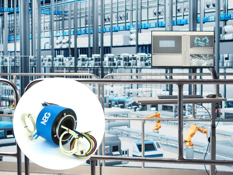
Contemporary industrial systems require real-time Ethernet connectivity on rotating machinery. A revolving electrical interface that allows Ethernet signals to move from a stationary network to a spinning structure is called an Ethernet through-hole (hollow shaft) slip ring. Shafts, fluid lines, or cable harnesses can pass through the unit via its central bore. The article's objective is to examine the design concepts, key technical details, compatibility with industrial protocols, and potential applications of this specialized component. The through-hole form factor is the ideal option for Industry 4.0 integration, and standard slip rings lack the signal integrity required to handle Ethernet properly.
What Is an Ethernet Through-Hole Slip Ring?
The Through-Hole Architecture Explained
The construction of the hollow shaft (bore) comprises conductive rings positioned around a central aperture and spring-loaded brushes that maintain electrical contact as the shaft rotates. The center bore allows hydraulics and pneumatics to attach rotating unions, feed cables through, and link shafts or other mechanical components simultaneously. Through-hole designs can withstand higher currents, more circuits, and more robust industrial installations than capsule-type slip rings. Capsule-type slip rings work better in low-duty, small applications.
Why Ethernet Demands Specialized Slip Ring Design
Because Ethernet requires stringent impedance restrictions (100 Ω differential), low insertion loss, minimal crosstalk, and return-loss management, standard power/signal slip rings are ineffective. The three most significant issues influencing the rotary link's Bit Error Rate (BER) are insertion loss, return loss, and crosstalk. Ethernet channels often use gold-on-gold precious metal connections. They are long-lasting, corrosion-resistant, and offer steady, low-resistance connections.
Technical Specifications and Performance Parameters
Data Rate and Protocol Standards
Designed for 100 MHz bandwidth over Cat5e shielded cable with RJ45 or M12 D-coded connectors, Fast Ethernet (100BASE-TX) supports 100 Mbps transmission. Gigabit Ethernet (1000BASE-T) requires extremely accurate impedance matching at 250 MHz to transmit data at 1 Gbps. It further complicates the rotary interface design challenge.
Protocol compatibility includes EtherCAT, PROFINET, EtherNet/IP, POWERLINK, SERCOS III, MECHATROLINK-III. Ethernet through-hole slip rings must be configured properly to support these protocols without altering the signal.The rotary interface must be used to verify the stringent latency and jitter requirements of real-time protocols such as EtherCAT (cycle durations of 50 to 250 µs) and PROFINET IRT (minimum of 250 to 500 µs).
Mechanical and Electrical Specifications
The bore (inner diameter) typically ranges from 12.7 mm to 980 mm. The most frequently used industrial sizes are 25.4 mm, 38.1 mm, 50 mm, and 100 mm. Although some high-speed models can operate at 400-600 RPM, Ethernet channels are typically rated for higher speeds.
Standard through-hole Ethernet devices feature one to eight Ethernet channels and six to forty-eight additional power/signal circuits. Power circuit ratings, which allow you to transmit both power and data in the same assembly, are typically 10-25 A per ring at up to 440 VAC/VDC. Environmental protection features include standard versions with an IP54 rating and optional IP65 sealing for resistance to water jets and dust in outdoor or washdown settings.
Contact and Shielding Design
Internal wiring with matched impedance and ring geometry to prevent the 100 Ω differential pair from shattering when spinning. Ethernet pairs are individually shielded per channel, and the shielding is treated as a distinct circuit path to prevent EMI between adjacent power circuits. Standard RJ45 connections are available for plug-and-play cable termination, while M12 D-coded industrial connectors are available for locations requiring more robust, secure terminations.
Industrial Applications of Ethernet Through-Hole Slip Rings
Robotic Systems and Industrial Automation
While carrying control signals, sensor data, and real-time EtherCAT network orders, articulated robot arms must maintain constant joint movement. The central bore allows for unfettered rotation while providing space for driving shafts or actuator components. Because the through-bore format mounts directly on the rotating shaft without adding complexity, it is also suitable for rotary tables, indexing systems, and CNC machining centers.
Wind Energy and Additional Renewable Energy Sources
Sensor data and control signals for pitch control systems and nacelle yaw mechanisms are transmitted. through through-hole Ethernet slip rings.The central bore provides space for electrical or hydraulic driving lines. Gold-contact designs with IP65 protection and a service life of over 100 million rotations are required for continuous operation every day of the week.
Industrial Imaging and Machine Vision
Gigabit Ethernet through-hole assemblies transmit high-bandwidth image data from automated optical inspection systems, rotating inspection platforms, and camera turrets. The through-bore architecture is also used by CT scanners and other sophisticated medical imaging systems to transmit high-speed data channels and patient table mechanics simultaneously.
Systems for radar, defense, and antennas
Radar antenna pedestals and revolving surveillance platforms require constant Ethernet connectivity for control and real-time data logging. Additionally, coaxial RF feed-throughs and Ethernet circuits can work together thanks to the hollow shaft design.
Design and Selection Considerations for Engineers
Bore Size and Mechanical Integration
The largest component that will pass through the bore, such as the shaft OD, hydraulic line OD, or cable harness bundle diameter, should be considered when selecting the hole's inner diameter. Next, add a clearance margin in accordance with the manufacturer's tolerance specifications.
Mounting options include a flexible coupling on the rotor to compensate for any unevenness and a flange-mount stator. Avoid "hard mounting" both ends simultaneously, as this can accelerate brush wear. Within the designated run-out tolerances, the rotor and stator should remain concentric. They may cause uneven contact wear and signal instability if they are more than 0.1 mm out of alignment.
Protocol, Data Rate, and Shielding Decisions
You must provide the industrial Ethernet protocol (EtherCAT, PROFINET, or EtherNet/IP) and the required data rate during the quoting stage. Not every slip ring design is compatible with every protocol. Examine the EMI environment. Use shielded Ethernet channels and shielded cable assemblies (STP/S-FTP Cat5e or Cat6) if the installation is near motors, drives, or transformers. Make sure that the data and power are kept apart inside the ring body of hybrid power + Ethernet assemblies. It is necessary to separate and screen the Ethernet channels and power circuits physically.
Connector and Cable Compatibility
RJ45 male connectors are the standard patch-cable interface on most through-hole Ethernet slip rings. M12 D-coded industrial connections are stronger and seal better in harsh conditions. Instead of selecting them as a field modification, you ought to do so during the design phase. 100BASE-TX and 1000BASE-T can both be used with Cat5e cable, which has a bandwidth of 100 MHz. Cat6 provides Gigabit speeds with improved crosstalk margins in noisy environments.
Conclusion
Ethernet through-hole slip rings enable Industry 4.0 data flows without altering machinery operation by connecting stationary industrial networks to constantly moving machinery.
The most crucial point to keep in mind is that the device will function reliably for a long time under challenging conditions if the proper bore size, data rate rating, protocol validation, shielding design, and connector type are selected. Finally, advise the reader to consult the manufacturer's datasheets early in the design phase, request signal integrity validation reports (S-parameters, BER testing), and establish environmental protection ratings.
NBG Innovations Group Pte.Ltd.
#13-13A, International Plaza, 10 Anson Road, Singapore (079903)


Navigation
 HomeSustainable
Product