


Signal Transmission in Capsule Slip Rings: Noise & Stability
BY NBG
 2026-05-11
VIEWS: 480

Signal Transmission in Capsule Slip Rings: Noise & Stability
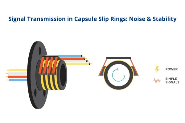
Capsule slip rings are small electrical connectors that spin. They are used in rotating systems with limited space, such as PTZ surveillance cameras, drone gimbals, robotic end effectors, small medical imaging heads, and test equipment. When full-size through-bore assemblies won't work, a 12 mm-diameter capsule can send both power and signals across a rotating interface.
A metal brush must maintain a reliable electrical connection with a rotating ring for an unlimited period without adding noise that corrupts the signals it carries. There are real effects from changes in contact resistance at the micro-ohm level. A 10 mΩ change at 100 mA signal current makes 1.0 mV of voltage noise, which is about the same as the full-scale output of a thermocouple that spans several degrees of temperature. For digital protocols like Ethernet, USB, CANbus, and HD-SDI, this same instability manifests as jitter, packet loss, and a drop in bit-error rate (BER).
Understanding Electrical Noise in Capsule Slip Rings
There are specific, identifiable mechanisms at the contact interface that cause noise in a slip ring. The first step to controlling a source through design and material selection is to understand each one on its own.
Resistive (Ohmic) Noise
The brush moving across the ring surface while the ring is spinning causes small changes in contact resistance, generating resistive noise. When conditions are dynamic, standard commercial capsule units exhibit a change in contact resistance of about 4-40 mΩ. When used the same way, high-end gold contact designs can handle changes of less than 1 mΩ.
The math directly affects the circuit: a 4 to 40 mΩ noise band at a 100 mA signal current produces 0.4 to 4.0 mV of voltage noise. Type K thermocouples output about 41 µV per degree Celsius, and a 350 Ω strain-gauge bridge may only produce a few millivolts at full load. Micro-cuts are even more disruptive. They are very short, high magnitude resistance spikes that can only be seen at oscilloscope bandwidths above 1 MHz.
Electromagnetic Interference and Crosstalk
Slip ring signal circuits can pick up EMI from nearby sources, such as motors, variable-frequency drives, transformers, and high-current power cables. In factories and places where robots work, the capsule unit is often only a few centimeters away from the motor windings. Inter-channel crosstalk occurs in the housing when signal energy couples inductively or capacitively between adjacent circuits.
Contact Related Noise Mechanisms
Three contact surface phenomena create unique noise signatures in addition to changes in bulk resistance. When the brush bounces off the ring for a short time during high-speed rotation or under external vibration, it creates temporary open-circuit events. Wear debris that builds up on the brush material creates temporary conduction paths that cause resistance spikes that don't depend on the brush's rotational position. Oxide and sulfide films build up on contact surfaces that aren't made of precious metals over months of use.
Factors Affecting Signal Stability
It's only useful to know where noise comes from if you can change the sources during the design stage. The following factors each have a direct, measurable effect on the stability of the signal throughout the life of the assembly.
Contact Material Selection
The material used for contact is the most important design choice for a capsule slip ring's signal performance. Pairs of gold-on-gold contacts have the lowest contact resistance of any solid metal sliding system. They also have stable surface chemistry (gold doesn't form oxide films under normal conditions) and exhibit the same behavior over a wide temperature range. Most high-performance assemblies use gold-plated copper rings and gold alloy wire brushes, made to ASTM B541 Au-Pt-Ag-Cu standards, to achieve the right balance between wear resistance, conductivity, and cost.
In humid or industrial environments, silver-based contacts can become sulfidated. Carbon and graphite brushes produce conductive wear debris that accumulates on ring surfaces, worsening noise over time. Because of electrochemistry, contact pairs of different metals also create new ways for things to break down that homogeneous gold systems don't have at all.
Mechanical Precision and Concentricity
The uniformity of brush contact force through each rotation is directly affected by the concentricity of the ring to the shaft. Eccentricity causes the resistance to change at the rotational frequency, which appears in the noise spectrum as a harmonic peak that moves with RPM. V-groove ring profiles (usually 90°) limit side-to-side movement of the brush, preventing the contact area from changing and reducing low-frequency noise.
Rotational Speed and Environmental Conditions
As the rotational speed increases, the dwell time at each contact area decreases. It makes dynamic contact resistance instability worse by reducing the natural averaging that helps mitigate low-frequency noise at lower speeds. When the slip ring is running at a high RPM, small bumps on the surface that would be bridged at low speed become temporary open-circuit events. The shape of the contact changes with temperature due to differences in thermal expansion rates. For outdoor PTZ installations or marine robotics, capsule designs need sealed enclosures and, if possible, positive-pressure purging to keep the contact area clean.
Contact Material Performance Comparison
Contact System | Dynamic Noise Floor | Corrosion Resistance | Debris Generation | Recommended Use |
Gold on gold | ≤1 mΩ | Excellent | Very low | Signal grade: all protocols |
Gold alloy on a silver ring | 3 to 8 mΩ | Good | Low | Light signal duty |
Silver alloy contacts | 5 to 15 mΩ | Moderate (sulfidation risk) | Low to medium | Power-only circuits |
Carbon/graphite brush | 40 to100 mΩ | Poor | High | Not recommended for signal |
Design and Integration Strategies for Noise Reduction
The baseline noise floor is set by choosing the right materials and ensuring the mechanical parts are precise. The strategies below deal with noise at the assembly, layout, and signal conditioning levels.
Shielding and Circuit Layout
In the capsule assembly, inter-channel crosstalk is managed by physical separation and the use of shielded channels for sensitive signals. The outer conductive housing should act as a continuous EMI shield, with a single ground point to keep ground loops from adding noise to the signal path. When shielded cables pass through the slip ring, the shield conductor is usually connected to the rotor and left floating on the stator.
The most important rule for layout is to keep high-current power circuits and millivolt-level analog signals completely separate. When both need to fit into the same capsule body, the power channels should be on one end of the assembly and the signal channels on the other, with a grounded guard channel in between them wherever there is enough room.
Filtering and Signal Conditioning
EMI filters that are directly connected to the slip ring's input and output connections stop high frequency conducted interference from getting to downstream circuitry, for situations where noise can't be completely controlled at the contact interface, such as sensitive analog circuits that are close to high power drives, transformer isolation, or optocoupler-based galvanic separation can act as a second barrier between the noise source and the signal path.
You need to match the impedance at 100 Ω and 75 Ω, respectively, to work with high-frequency data channels that carry Ethernet (100BASE-TX) or HD-SDI video. Unterminated or mismatched high speed lines passing through the slip ring cause signal reflections that worsen contact noise, turning a fine noise floor into visible data loss or frame errors.
Redundant Brush Contact Design
In a dual-brush setup, two brushes contact the same ring at different angles, creating parallel conduction paths and reducing variation in effective resistance. If one brush hits a dirty spot or an uneven surface, the other keeps the flow going. It stops the micro-cut event that would happen with just one brush.
Testing and Validating Signal Performance
It is important to choose the right contact materials and geometry, but that is not enough. Performance must be measured under the same conditions the assembly will face. The following test methods go from simple checks of incoming items to full protocol-level validation.
Static and Dynamic Contact Resistance Measurement
Static contact resistance, which is measured with a precision milliohm meter when the object is not moving, is a standard quality check during incoming inspection. Standard commercial designs should have a variation of about 10 mΩ around the ring's circumference. Premium gold-contact units should have a variation of ≤1 mΩ.
Signal Integrity and Protocol Level Testing
Resistance measurements show how the interface works, but they don't tell you how well the protocol will perform. For digital channels, protocol level validation is necessary even when the assembly is always turning. Extended environmental testing, which includes rotating the shaft for extended periods while changing temperature and humidity and applying mechanical vibration, is the only way to detect wear driven noise degradation that only shows up after millions of shaft revolutions.
Test Method | What It Reveals | Adequacy |
Static resistance only | Baseline quality at one position | Insufficient alone |
Dynamic Noise | Overall transmission quality | Comprehensive |
Spectrum/frequency analysis | EMI harmonics, RPM-correlated noise peaks | Comprehensive |
Protocol-level BER test | Live packet loss, jitter, frame errors under rotation | Comprehensive |
life cycling test | Wear driven degradation over service life | Comprehensive |
Application Considerations
Sending signals over long distances is one of the hardest things to do with capsule slip rings, which is why PTZ and CCTV surveillance cameras are so hard to use. A single unit must constantly send HD-SDI or Ethernet video over a platform that can spin thousands of times a day without dropping frames. Impedance-matched 75 Ω channels and a fully shielded housing are not extras; they are needed for the product to work. Drone gimbals and robotic end-effectors make the problem worse by adding more vibration.
Thermocouples, load cells, and strain gauges are used in test and instrumentation applications that only have full-scale outputs of a few millivolts. The ≤1 mΩ dynamic noise specification is a functional threshold, not a way to separate products into different levels. Medical applications merge the miniaturization constraints of sub-15 mm capsule designs with EMC certification criteria. Signal degradation in imaging or diagnostic situations has immediate clinical effects, which is why it is important.
Conclusion
The chemistry of the contact material, the design of the springs, mechanical concentricity, environmental exposure, and EMI handling all affect the noise and signal stability of capsule slip rings. For work that is important to the signal, the minimum performance level is gold-on-gold contact pairs with a dynamic noise specification of ≤1 mΩ. It gets even better when you add fiber brush redundancy, shielding for each channel, a disciplined circuit layout, and impedance matching. The only way to be sure that a capsule slip ring won't become a source of noise that breaks the system built around it is to record dynamic waveforms and test protocol-level BER in real-world conditions, including rotation.
NBG Innovations Group Pte.Ltd.
#13-13A, International Plaza, 10 Anson Road, Singapore (079903)


Navigation
 HomeSustainable
Product