


Through Hole Slip Rings for Rotary Tables and Indexing Systems
BY NBG
 2026-04-21
VIEWS: 869

Through-Hole Slip Rings for Rotary Tables and Indexing Systems
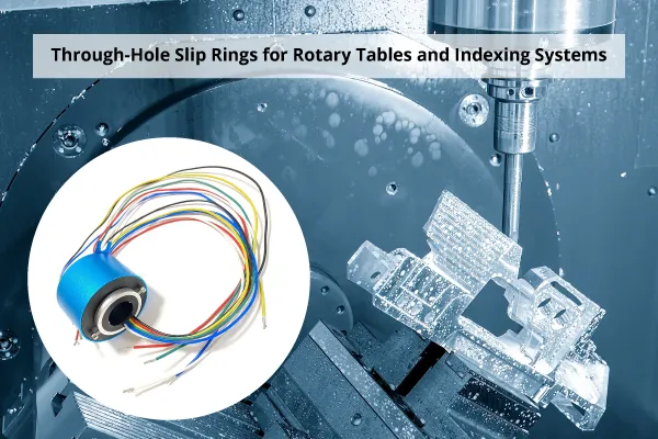
CNC rotary tables and multi-station rotary index tables need a constant flow of power, signals, and media to their moving parts. Using traditional wiring methods can lead to mechanical failures, downtime, and wires everywhere. By passing all utilities through a central bore, through-hole (hollow shaft) slip rings address this issue and facilitate connection to stationary center columns. Anatomy, key features, hybrid signal/media capabilities, selection criteria, and usage examples are all included in article previews.
What Is a Through-Hole Slip Ring?
Hollow Bore Architecture
The central hole (bore) of a rotating electrical junction allows shafts, cables, hydraulic or pneumatic lines, or other components to pass through. Brush/ring assemblies maintain continuous contact between the rotor (spinning) and stator (stationary) components during 360° of unrestricted rotation. The primary structural advantage of these over solid-shaft capsule slip rings is their hollow core. Also referred to as a bore slip ring, through-bore slip ring, or hollow shaft slip ring.
Why Rotary Tables Demand The Architecture
Power, communications, and air pressure must always be available for index tables with more than two stations operating in the same direction. Because it has a modest footprint and doesn't need to be mounted outside or on the ceiling, the fixed center column design, which is typical of index tables in the RT and TMF series, is the best option for mounting a slip ring stator. Eliminates the need for cable festoon systems around the edge of the table and prevents harm to the wire wrap.
Core Technical Specifications
Bore Diameter and Outer Dimensions
The typical bore size ranges from 12.7 mm to 300 mm, and large ring indexers may require even larger bore sizes. The bore size of some LPT series units is 980 mm. The shaft diameter, the size of the hydraulic and pneumatic lines passing through the center, and the machine's total dimensions all play a role in the decision.
12.7 mm, 25.4 mm, 38.1 mm, 50 mm, 60 mm, 80 mm, and 100 mm are the standard bore steps. For instance, a 25.4 mm bore has an outer diameter of roughly 86 mm, and a 100 mm bore has an exterior diameter of roughly 185 mm. The outer diameters scale proportionately.
Circuit Count, Current, and Voltage Ratings
Although you can alter them beyond the default settings, most circuit counts fall between 2 and 108 rings. Each circuit's current ratings typically range from 2A (signal) to 10A (power). High-amperage models can handle three-phase 480V power. The difference in dynamic contact resistance is within 10 mΩ, depending on speed and design, while insulation resistance is typically at least 500 MΩ at 500 VDC.
Rotational Speed and Operating Temperature
While high-speed models can withstand up to 1,500 RPM, standard industrial through-hole slip rings can only withstand 250 to 300 RPM. Typically, the operating temperature range is between -40°C and +80°C. It matters what the connections are made of. Compared to silver-graphite contacts, gold-gold precious metal contacts are more durable and offer superior signal stability for high-cycle applications.
Signal and Power Transmission Capabilities
Industrial Fieldbus and Ethernet Protocols
Contemporary through-hole slip rings are compatible with all major industrial communication protocols: Profinet, EtherCAT, DeviceNet, CANbus, Profibus, RS485/422, Modbus, Ethernet (100BASE-TX/1000BASE-T), and USB.
Twisted-pair wiring is necessary for Ethernet and Profinet channels inside the slip ring. As a result, they are less susceptible to electromagnetic interference (EMI), which can disrupt communication and create outages. Gigabit Ethernet channels (1000BASE-T) with through-bore configurations with a bore diameter of up to 100 mm are now available.
Power Transmission — Low Voltage to Three-Phase High Voltage
Multiple fixture stations can simultaneously receive high-voltage 480V three-phase power and low-voltage DC control power from a single device. Installation time is reduced by using flying lead configurations, which allow you to connect the panel without hardwiring it during machine setup.
Encoder and Sensor Signals
Slip rings are great for sending encoder signals, RTDs, and thermocouples, including K-type thermocouples, with high accuracy. This is especially important for indexing axes that use closed-loop position feedback. Using only signal or shielded circuits will keep power channels and sensor lines from interfering with each other.
Hybrid Integration — Electrical Transmission with Pneumatics and Hydraulics
Rotary Union and Slip Ring Combinations
Air or water-powered rotary unions are a good fit for the through-bore design. The media path passes via the center of the electrical rings, which encircle the vacant center. Power and signals can be transferred between hybrid assemblies without interfering with one another.
Additionally, they are capable of transporting heated oil, hydraulic fluid, cooling water, compressed air, and vacuum. Depending on the seal's design and rotational speed, high-end hybrid systems can withstand pneumatic pressures of up to 100 bar. Radial or axial media ports on the stator housing are typically M5, 1/8, 1/4, 3/8, or 1/2 inches in size.
Why This Matters for Indexing Table Applications
Since everything passes via the central column, there is no need for overhead pipes or separate external rotary unions. Pneumatic valve banks on rotating fixture plates can be powered and controlled by a single device. It reduces the machine's size, simplifies cable management, and minimizes assembly costs.
Environmental Protection and Service Life
IP Ratings and IEC 60529 Compliance
According to IEC 60529, through-hole slip rings can have an IP rating from 00 (open) to 68 (submersible). IP54 is usually the best choice for routine automation and machining center settings because it keeps dust out and is splash-proof. It is crucial to ensure the bore entrance is properly sealed, as the hollow bore is often the most vulnerable access point.
You should request IEC 60529 test documentation from your vendors. However, because they are more expensive and can make it more difficult to reach the bore, you should not request higher IP ratings unless the environment truly requires them. The evaluation needs to match the actual circumstances.
Contact Material and Expected Service Life
Gold-on-gold contact surfaces can rotate up to 50 million times without changing their contact resistance very much. For most industrial duty cycles, silver-alloy fiber brush technology requires no maintenance and produces very little noise and friction. Contact wear is influenced by several key factors, including RPM, circuit count, current load, and exposure to contaminants.
Selection Guide — Matching the Right Slip Ring to Your Application
Step 1 — Define the Bore Size Requirement
Create a map of every utility that must pass through the center, including the cable bundle diameter, drive shaft diameter, and pneumatic hose OD. Choose the next standard bore size that is larger than the minimum you discovered, accounting for a margin of error. To prevent tools from reaching the center zone, the bore of ring indexers with large through-hole tables (TSR series) might need to be 100 mm or larger.
Step 2 — Enumerate All Electrical and Media Channels
Record every circuit, including the solenoid valve control lines, encoder wires, fieldbus channels, signal lines, power phases, and thermocouple pairs. A ring circuit is required for every wire or twisted pair. Underestimating the number of channels is the most frequent sizing error. To avoid having to replace the slip ring when you switch tools in the future, add 20-30% extra circuits.
Step 3 — Confirm Protocol, Environment, and Mounting
Verify the fieldbus protocol and cable type (use Cat5e shielded cable for Profinet/Ethernet channels). Indicate the IP rating required for the environment (dust, wash-down, coolant mist) in which it will be utilized. Verify the mounting interface, including the axial/radial lead exit direction, the stator's anti-rotation torque support, and the rotor flange pattern. Request documentation of certified tests, such as IP rating test results, ISO 9001, RoHS, and CE certifications.
Industry Applications
Power, coolant, and encoder signals are sent to CNC machining centers and rotating worktables via a single bore-mounted unit. High-cycle index tables with built-in slip rings or rotary union combinations, pneumatic clamps, and PLC connectivity are all used in automotive body shop assembly lines.
A slip ring in the center column of the seventh-axis rotating tables for cooperative robots transmits air, pendant signals, and servo power to the grippers. Packaging and labeling machines employ these systems for per-station fieldbus control and multi-station indexing. Stainless steel housings with IP65 or higher ratings and clean media routing are used in food and drink automation.
Conclusion
There aren't many through-hole slip rings. For them to work reliably over a long period of time, the bore size, circuit count, protocol compatibility, hybrid media integration, and environmental protection must all be just right. To avoid the need to rework the machine during construction, engineers are encouraged to contact slip ring manufacturers early in the design phase and to use a complete list of channels.
NBG Innovations Group Pte.Ltd.
#13-13A, International Plaza, 10 Anson Road, Singapore (079903)


Navigation
 HomeSustainable
Product