


Avoiding Signal Interference in High Density Capsule Slip Rings
BY NBG
 2026-06-18
VIEWS: 961

Avoiding Signal Interference in High-Density Capsule Slip Rings
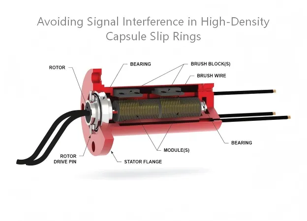
As capsule slip rings improve, they can accommodate 12 to 72, or more, circuits in housings with an outer diameter of less than 50 mm. This feature makes it easier for noise to happen because the electrical parts are close together. Conductive rings with a pitch of less than 2 mm, interleaved power and signal wiring, and high-frequency data channels all share a small metal space. It is not a theoretical problem for design engineers who are specifying slip rings for robotics, pan-tilt-zoom (PTZ) cameras, medical equipment, surveillance platforms, and industrial automation. Signal interference in high-density capsule slip rings results in quantifiable reductions in data throughput, bit error rate (BER), and overall system reliability. This article discusses the main ways interference occurs and the layered engineering methods used to prevent it.
Understanding Signal Interference Mechanisms
Before using any mitigation strategy, you need to understand exactly how interference enters and spreads through a high-density capsule slip ring. There are three coupling mechanisms at work, and each requires a different engineering response.
Electrostatic (Capacitive) Coupling
A distributed capacitor is made up of every pair of conductive rings that are next to each other. The coupling current between them increases with increasing signal frequency and decreases with decreasing ring spacing. In high-density designs where the axial ring pitch is less than 2 mm to fit more circuits, this capacitance becomes a real crosstalk path. High-frequency signals on one channel look like noise on nearby channels. The effect worsens at data rates above a few megahertz, which is a significant problem for modern industrial Ethernet and HD-SDI video channels.
Magnetic (Inductive) Coupling
Power channels that carry current make magnetic fields. When a high-current AC power channel is next to a low-level signal circuit, such as in mixed power-and-data slip ring assemblies, the changing magnetic field induces a voltage in the signal wiring loop. The induced voltage depends on the area of the loop formed by the signal conductors. Bigger loops catch more flux. For this reason, managing the wiring of the slip ring's lead assembly is just as important as the ring's shape.
EMI and Radiated Noise
High-frequency noise travels along power and signal conductors as conducted electromagnetic interference (EMI). Radiated EMI, on the other hand, comes from outside sources like servo drives, brushless motors, or the switching transients of the slip ring's own power channels. At higher data rates, signal conductors can act like antennas by both sending and receiving radiated noise. The difference between conducted and radiated EMI determines which suppression method to use. In a well-designed installation, both types of EMI may need to be addressed simultaneously.
Contact Material Selection and Electrical Noise
The materials that make up the brush-ring interface directly affect the electrical noise floor. Gold-on-gold contacts are the best choice for signal-channel applications for several reasons: contact resistance stays low and stable (usually below 10 mω in well-maintained assemblies), and gold's corrosion resistance prevents the formation of an oxide layer, which causes intermittent resistance spikes and noise bursts. Silver-graphite contacts are better for power channels than for precision signal paths because they are cheaper and last longer. Still, they produce more particulate debris and exhibit greater variation in contact resistance.
The brush's architecture also matters.Multistrand brushes configurations have more than one parallel contact path per channel. It means that multiple contact points work in parallel, reducing the probability of complete signal break and smoothing out resistance fluctuations, which lowers effective noise. The trade-off is that drag torque increases and the mechanics become more complicated. Monowire Brushes are easier to use, but they are more likely to make noise when they hit something or become clogged with debris.
Lubrication, often forgotten, is an important factor in maintaining noise stability throughout the life of the assembly. Synthetic formulations, such as Pennzane-based oils, maintain a consistent film thickness over a wide range of temperatures, keeping the contact interface stable and preventing gradual noise degradation that occurs when contacts are dry or dirty.
Shielding Strategies for EMI Suppression
After the contact interface has been optimized for low noise, the next layer of protection addresses electromagnetic interference from outside the assembly or radiated between internal channels. Shielding at different levels, like the enclosure, ring stack, and cable, works together to stop both conducted and radiated EMI.
Conductive Housing and Enclosure Shielding
The first line of defense against EMI from outside sources is a fully metal enclosure with a continuous, well-grounded shell. The effectiveness of a shield depends on three factors: how well the material conducts electricity, how thick the wall is, and whether there are any gaps or seams. A single unshielded opening, such as an unmated connector port or a housing seam without a conductive gasket, can reduce shielding effectiveness by 20 dB or more at higher frequencies. To maintain the enclosure's shielding to the conductor shield, EMC-rated cable glands are required at every cable entry point.
Guard Rings (Shielding Rings)
Inserting grounded conductive shielding rings, also called guard rings, between sensitive signal and high-current power channels within the ring stack itself breaks up capacitive and inductive coupling paths. The penalty is axial length: each guard ring occupies space in the stack, increasing the slip ring body's overall length. In compact capsule configurations, every millimeter of axial growth affects the host assembly. It is a real design trade-off. Some manufacturers fix this by installing guard rings only between the power section and the most sensitive communication channels, not between every circuit pair.
Cable Shielding and Grounding Strategy
Shielded twisted-pair or coaxial cables are often used at the rotor and stator ends of signal channels. You should really think about grounding those cable shields. Single-end grounding stops ground loops at low frequencies, but it doesn't work as well as shielding above 1 MHz. Double-end grounding improves high-frequency performance, but it also creates a loop area that can pick up magnetically induced currents at power-line frequencies. In systems that have both power-line and high-frequency signal content, a hybrid approach—single-end grounding with high-frequency bonding at the second end via a small capacitor—can meet both needs simultaneously.
Channel Layout and Signal Isolation
Shielding handles interference that has already entered the assembly, but a well-planned channel layout can stop many coupling paths from forming in the first place. The way power and signal circuits are physically configured in the ring stack directly and measurably affects crosstalk and noise.
Physical Separation of Power and Signal Channels
The easiest way to fix the problem is to place all the power channels at one end of the ring stack and all the signal and data channels at the other. Non-conductive divider or separator plates between the two sections break up direct coupling paths and give the shielded area some electrical isolation without adding any conductive material. For bigger groups that need a lot of data, the best way to isolate communication channels is to put them in a separate internal sub-assembly. Still, it makes the assembly harder to put together and bigger on the outside.
Impedance-Matched Design for High-Speed Data
For protocols that require controlled-impedance transmission, such as 100Base-T and 1000Base-T Ethernet, USB 3.x, and HD-SDI, the signal integrity problem extends beyond simple noise pickup. The three most important factors affecting the data integrity of an Ethernet slip ring are insertion loss, return loss, and near-end crosstalk (NEXT). Each one needs to be managed separately from the fixed wiring that goes across the rotating interface.
Coaxial capsule slip-ring architectures meet RF channel needs by maintaining a constant characteristic impedance across the rotating joint, improving the voltage standing wave ratio (VSWR), and reducing crosstalk between channels. These designs are necessary when the slip ring must pass frequencies above a few hundred megahertz.
The table below shows how signal type, key parameters, and preferred architecture are related:
Signal Type | Key Parameter(s) | Preferred Architecture |
Analog sensor (DC–10 kHz) | Contact noise, resistance stability | Gold-on-gold, shielded lead |
Industrial Ethernet (100/1000Base-T) | Insertion loss, return loss, NEXT | Impedance-matched twisted pair |
HD-SDI / analog video | Return loss, bandwidth | Coaxial channel, low-loss contacts |
RF/microwave (>100 MHz) | VSWR, inter-channel isolation | Coaxial capsule slip ring |
High-power AC/DC | Separation from signal, thermal | Dedicated power section, guard rings |
Signal Conditioning and Filtering
EMI filters are installed at the input and output connections to prevent high-frequency transients from entering or leaving the slip ring. Placement is important: filters work better when they are as close as possible to the slip ring interface because they catch noise before it has a chance to travel down the lead assembly. Optocouplers, or signal transformers, completely separate the source and load circuits, providing galvanic isolation, which is often required in medical or safety-critical applications. It stops the common-mode current path that noise must travel along.
Grounding Best Practices
Noise current needs a low-impedance return path to move around safely instead of showing up at signal nodes. Proper grounding gives it that path. Dedicated grounding brushes maintain the rotor-to-stator ground connection continuously, regardless of rotor speed or direction. It ensures that the metallic housing and guard rings remain at a specific potential.
The most common grounding mistake in multi-path assemblies is adding more than one uncontrolled ground return path. It makes ground loops happen by accident. A ground loop is a large conductor loop that acts as a receiving antenna for magnetic fields, turning them into common-mode currents on the signal cabling. The answer is to have one clear ground reference point to which all other shield connections are intentionally connected, not by accident. In practice, an ungrounded shield doesn't protect against any frequency. The shield will only work if the ground connection is good.
EMC Standards and Compliance
The IEC 61000 series is the main international standard for emissions and immunity requirements. It also sets the rules for system-level EMC compliance for industrial slip ring assemblies. IEC 61000-6-2 (immunity) and IEC 61000-6-4 (emissions) are the two most relevant generic standards for industrial settings. Testing for immunity usually includes IEC 61000-4-2 for electrostatic discharge, IEC 61000-4-3 for radiated immunity, and IEC 61000-4-6 for conducted immunity.
A very important point that is often missed in procurement specifications is that EMC compliance must be verified at the system assembly level, not just the slip ring component. The way the slip ring interferes is directly related to how its cables are set up, how it is grounded, and how close it is to other sources of noise in the installation. A pass at the component level does not guarantee compliance at the system level.
A Systems Level Approach
There isn't just one way to keep signal integrity in a high-density capsule slip ring installation. Choosing the right contact material sets the noise floor, but it doesn't address EMI from nearby drives. Shielding the enclosure protects against external fields, but it doesn't help with capacitive coupling between adjacent rings. Guard rings break up the coupling between stacks, but they also increase their length. All shielding measures work when they are properly grounded. If they aren't, they can make performance worse by creating loops.
The best way to deal with interference is to treat it as a system problem that is solved in layers: material selection, mechanical layout, shielding, grounding, cable management, and external filtering. Each layer adds to the noise budget that the next layer must deal with. As the number of channels increases and the need for faster data rates approaches the gigabit range, proactive EMC design is moving from a compliance requirement to a way to stand out from the competition.
NBG Innovations Group Pte.Ltd.
#13-13A, International Plaza, 10 Anson Road, Singapore (079903)


Navigation
 HomeSustainable
Product