


CT Slip Ring Failure Causes and How to Prevent Them
BY NBG
 2026-08-24
VIEWS: 860

CT Slip Ring Failure Causes and How to Prevent Them
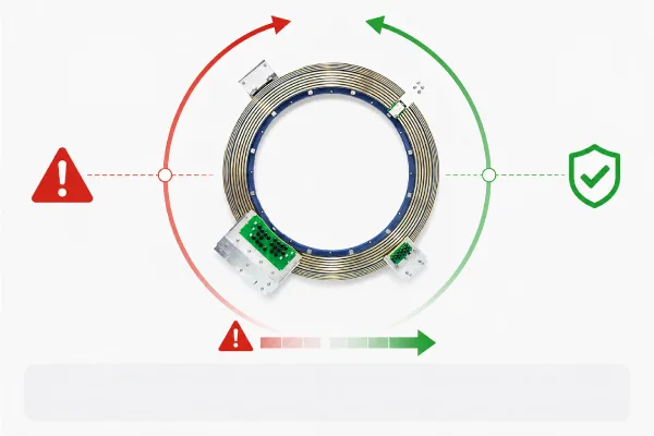
The slip ring is the electrical and data link that turns and is at the heart of every CT gantry. While the gantry spins, it sends high-voltage power to the X-ray tube on the spinning frame and raw image data from the detector array back to the stationary acquisition system. This is done without a single wire getting tangled. When this interface breaks down, it leads to image artifacts, persistent "gantry not ready" errors, and unexpected downtime that forces patients to be rescheduled and keeps biomedical engineering teams busy for days.
The first step in protecting both image quality and scanner availability is to learn about the five most common ways that a CT slip ring can fail and how to stop each one.
How a CT Slip Ring Works (and Why It Fails)?
A CT slip ring is made up of a set of precise conductive rings that are usually machined from copper or copper alloy and then gold- or silver-plated to protect them from corrosion. These rings are attached to the moving gantry frame. Stationary carbon or silver-graphite composite brushes press against these rings with controlled spring tension, making sure that the electricity stays connected. The rotating unit is held up by wire-race or precision ball bearings, which keep the ring-to-brush gap stable over millions of turns.
The duty cycle never ends. Modern CT scanners can spin at up to 3–4 revolutions per second around a ring that can be almost 2 meters in diameter. Over the course of their life, the scanner will have done hundreds of millions of rotations. There is slipping friction every time the wheel turns. That friction makes wear debris, heat, and carbon dust, which are the main things that break things down. The conditions for failure are always present in a hospital setting, with its humidity, disinfectant vapors, and airborne particles, as well as the electrical stresses of high-voltage power delivery. The sections that follow talk about how these conditions show up.
Common CT Slip Ring Failure Modes
There are various failure modes observed in a CT slip ring, and some of these are discussed as follows:
Failure 1 — Signal Interruption
Often, the first failure mode that hospital staff notice is a signal interruption. Some signs include scans that stop working sometimes, "gantry not ready" messages that don't make sense, data timeouts during acquisition, and scans that finish but produce useless images because they lack projection data. Here, three root causes come together.
Contact wear is the main cause: the brush material and ring surface wear away from constant friction until the contact pressure drops below the level needed for a reliable electrical path. The process goes faster when it's contaminated. The carbon dust that the brushes leave behind mixes with water and flying particles to make a film that sticks to the ring tracks.
Lastly, corrosive agents common in hospitals (hydrogen sulfide from dirty city air and aldehydes in disinfectants) break down copper tracks and their plating, which raises interface resistance even on rings that don't seem to be wearing down. When inspecting, the most important things to look for are ring surfaces that are grooved or discolored and a lot of carbon buildup around the brush holds.
Failure 2 — High Electrical Noise
There is a lot of electrical noise at the slip ring interface, which causes streak artifacts, concentric ring patterns, and signal spikes in reconstructed images. These artifacts worsen at faster rotation speeds and can look like pathology, which is a safety concern for the patient and has nothing to do with the mechanical fault itself.
The mechanisms are linked: fretting-induced brush oscillation changes the signal path at high frequency; micro-arcing at points of broken contact adds broadband noise directly to the circuit; and electromagnetic interference couples into low-level signal channels that share the same rotating frame.
Because the detector signals that are being messed up are analog and low-amplitude before they are digitized, even small amounts of noise introduced at the interface lower the quality of the picture long before a power delivery problem is noticeable. To meet the EMC standards of IEC 60601-1-2, the slip ring assembly can't make noise. However, wear and dirt make this standard less and less reliable over time.
Failure 3 — Increasing Contact Resistance
When a brush touches a ring, the ohmic resistance at that point is controlled by the real contact area made up of microscopic bumps (called "a-spots"), the contact force, and the state of the surfaces that are touching. When any of these things get worse, pushback goes up.
Fretting corrosion is the main cause of CT slip rings. The tiny movements that happen during a sliding contact break and rebuild the thin oxide layer on the metal surfaces over and over again.
Each break in the surface exposes new metal to oxidation. Over time, a layer of metal oxides and wear particles builds up faster than the slide motion can move it, creating a thick, high-resistance film across the contact zone. Not enough brush spring pressure (which lets the brush bounce instead of staying in contact), loss of precious metal plating, and current-induced
Failure 4 — Mechanical Wear and Bearing Issues
Popping when the gantry turns, more drive torque, and measured vibration. Bearing wear and raceway pitting, shaft imbalance or too much runout (total indicator runout, or TIR), poor or worn-out lubrication, and brushes that rock instead of cleanly tracking the ring surface are some of the main reasons.
Mechanical wear is especially harmful to systems because it creates a feedback loop: vibrations caused by bearings make the brush-ring interface fret more, which speeds up the growth of both contact resistance and electrical noise.
Failure 5 — Data Transmission Errors
Modern CT scanners with multiple slices and photon counting create image data at gigabit-per-second rates, which is much faster than what copper rings can safely handle. As a result, projection data moves from spinning to stationary components without touching them. This can be done using optical couplers, which consist of rotating LED or laser sources connected to stationary photodetectors, or capacitive and near-field RF links.
These channels have unique failure signs, such as rising bit error rates (BER), CRC failures, packet loss, or projection data that isn't working right, which causes picture artifacts that aren't the same as contact noise patterns.
Carbon dust from brush wear is the main enemy of optical data channels because it covers coupler lenses and lowers optical transmission efficiency. Misalignment of the rotating lens or antenna assembly due to mechanical issues, worn-out connectors on the interface PCBs, and clock or jitter problems in the serializer/deserializer chain are other reasons.
How to Prevent CT Slip Ring Failure?
Some of the preventive measures you can take to avoid CT slip ring failure are as follows:
Material Selection
Gold-plated rings, silver-graphite, or silver-alloy fiber brushes are all examples of precious metal contact materials that are good for hospital settings because they have low, stable contact resistance and rust resistance. Arcing is less likely to happen at high-voltage channels when the coating thickness, creepage distances, and insulation spacing are all right. Corrosion-resistant materials and surface treatments also make the equipment last longer in places where disinfectant vapors can't be avoided.
Manufacturing Precision
Tight concentricity tolerances and low TIR reduce the fretting caused by vibrations that start the growth of contact resistance. Carbon builds up between tracks and clogs optical channels. To stop this, brush holders are made with controlled brush geometry, measured spring pressure, and designs that eliminate dust dead zones. Assembly-level flaws don't reach the field because of strict quality control measures, such as checking for loose copper strands that can cause arcing at high-voltage rings.
Reliability Testing
Accelerated life testing, measured in rotation cycles similar to the scanner's expected service life, ensures that contact resistance and noise levels remain within acceptable ranges at the end of their useful lives. Insulation resistance testing shows that the dielectric is still good across channels, and EMC proof shows that the product meets the requirements of IEC 60601-1-2.
Preventive Maintenance
A slip ring will last longer if the ring tracks and optical coupler lenses are inspected and cleaned regularly, the brushes are replaced when they reach the wear-indicator limits, and the scanner maintenance record is carefully filled out.
Biomedical engineers can find signs of wear and tear on scanners before they become defective by using condition monitoring tools like multimeters, insulation resistance testers, and the scanner's built-in diagnostics for brush resistance and signal consistency. It costs a brush set to catch a rising contact resistance signature early. If you wait too long, it can cost a ring assembly, a service call, and a day of missed meetings.
Conclusion
A small group of interconnected issues causes most CT slip ring failures. These include mechanical wear that leads to contact resistance growth through fretting; contamination from carbon dust and environmental corrosives that hurts both the contact surface and the optical data channel; and bearing problems that make all the other failure modes happen faster. These don't work by themselves, and they don't all answer to a single-point fix.
The best way to prevent harm is to use the right materials for the job at the design stage, make sure the product is manufactured precisely so there is little fretting from the start, test it for reliability to make sure it works in real-life situations, and do regular preventative maintenance to catch damage before it gets to the patient.
If you need help with your scanner model and how often it needs to be serviced, you can look at the service documentation from the scanner's manufacturer or talk to a qualified medical imaging service engineer.
NBG Innovations Group Pte.Ltd.
#13-13A, International Plaza, 10 Anson Road, Singapore (079903)


Navigation
 HomeSustainable
Product