


7 Key Design Challenges of High Speed CT Slip Rings
BY NBG
 2026-08-17
VIEWS: 872

7 Key Design Challenges of High-Speed CT Slip Rings
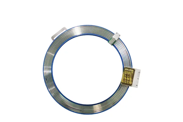
The slip ring is the electromechanical brain of the CT gantry. It's a precise interface that sends kilowatts of power and gigabits of detector data across a rotating assembly that's one to two meters in diameter without having to wrap cables around it. The gantry has to turn faster and faster in modern CT systems. For cardiac and free-breathing imaging, it now takes about 0.23 to 0.25 seconds per spin, which puts a lot of stress on every part of the system.
To design a high-speed slip ring for CT, you have to address seven mechanical, electrical, and heat issues that affect each other at the same time. Solving one problem often makes another worse. This is a real systems-engineering problem. This piece breaks down the problems OEM design engineers and system integrators face.
Challenge 1 — High-Speed Rotation Reliability
Rotational speeds and g-loading
Most CT gantries spin at speeds between 120 and 280 RPM. When spinning times are less than a quarter of a second, peripheral parts are subject to tens of g of centripetal load. Every gram of imbalance is greatly increased when moving fast, so it is very important to pay close attention to how the mass is distributed across the rotating assembly.
Bearing and balance engineering
Wear on the main bearings and a lack of lubrication are the main reasons why gantries break. Dynamic balancing that meets standards like ISO 1940 and accurate tolerancing are both important for long-term dependability. System downtime is directly related to the choice of preventive bearings and how they are oiled.
Contact stability under vibration
Micro-vibrations and shocks can temporarily break the contact between the brush and the ring, which can mess up data and power delivery. To keep reliable contact across the whole working speed range, the contact geometry, the design of the preload spring, and the compliance of the brush holder must all be fine-tuned.
Challenge 2 — High-Bandwidth Data Transmission
Data-rate problem
A lot of raw picture data is made by multi-slice and dual-source detectors. Transfer speeds have gone from tens of megabits per second in early CT systems to multiple gigabits per second in more modern ones. These speeds will continue to rise as detector sharpness and scan speed increase.
Why does contact fail at speed?
High-speed digital signals can't be sent consistently through sliding brush contacts. Contact-resistance modulation adds noise and signal variation that messes up the bit stream. This means that standard electrical slip rings aren't good enough for today's data rates in the data channel.
Contactless architectures
Optical (fiber/LED-laser) and capacitive/near-field coupling are now the most common ways to transfer image data. Vendors say that rates that have been applied start at about 10 Gbit/s, and that rates that are planned to be added will reach hundreds of Gbit/s.
Hybrid power + data assemblies
Modern CT slip rings have both kilowatt power rings and Gbit data channels on a single rotating structure. They do this by combining power sliding contacts with data contactless links in a small package.
Challenge 3 — Signal Integrity Protection
Bit error rate (BER) targets
CT scan data needs to be sent almost without any errors. The bit error rate goes up because of jitter, impedance mismatch, and signal reflections. Even small increases in BER can lower picture quality or require expensive retransmission. Because of this, signal integrity is one of the most important design constraints.
Transmission-line behavior
The large-diameter ring structure works like an RF transmission line when data rates are high. To keep uneven path lengths, impedance breaks, and echoes under tight control, you need strong matched-impedance design and layout skills.
Galvanic isolation
To keep leaky currents and high-voltage transients from getting into noise-sensitive channels, the data measurement system needs to be separated from the spinning gantry. Galvanic isolation is an important part of the architecture and shouldn't be overlooked.
Channel separation
Crosstalk between nearby power and data channels needs to be kept to a minimum by shielding them and carefully planning their layout. With each new CT generation, this gets harder because more and more lines have to be packed into a smaller space.
Challenge 4 — Electrical Noise Reduction
Noise sources
The CT slip ring operates in an electrically challenging environment. Changes in contact resistance, micro-arcing, the formation of oxide films, and EMI from nearby drive motors, variable-frequency drives, and the high-voltage generator cause a challenging noise floor.
EMC/EMI design measures
To reduce damage, you need dedicated shielded channels, EMI filtering on all I/O, low-impedance grounding to stop ground loops, and RF shielding between the rotor and stator parts. These safety features need to be built in from the beginning; adding protection after the fact rarely works well enough.
Contact-material selection
Precious metal fiber-brush contacts, usually made of gold, silver, or palladium alloys, keep contact resistance stable and cut brush-generated noise by a huge amount compared to regular copper or carbon contacts.
Contactless advantage
Optical data lines don't get affected by electromagnetic interference, so the data path doesn't have to deal with noise at all. Because of this, contactless data architectures are a very strong choice in CT design.
Challenge 5 — Thermal Management
Heat sources
The main thermal loads are heat from the power rings and heat from friction at the brush surfaces. In new CT systems, the current, speed, and number of channels all go up, which makes more heat.
Thermal feedback loop
Too much heat increases contact resistance, which creates more Joule heat. This speeds up wear and increases the risk of oxidation or distortion. If you don't fix this positive feedback loop, it can quickly break down in a chain reaction.
Cooling and materials strategies
To manage heat well, you need high-conductivity contact materials, structures that dissipate heat, forced-air or liquid cooling systems, and materials that are thermally matched and keep the contact pressure constant across the operating temperature range.
Challenge 6 — Long Service Life Requirements
Duty cycle in clinical use
In hospital settings, CT scanners are used almost all the time, and they often work during more than one shift. Because maintenance windows are short and don't happen very often, all rotating parts, including slip ring elements, must be able to handle long periods of high-speed operation with minimal assistance.
Wear management
Wear-indicator features can be added to multi-layer contact and brush systems with valuable metal fiber brushes. This lets you know before contact failure impacts performance and extends service life.
Contactless = maintenance-free
Optical and capacitive data links eliminate the need for sliding contacts on the data path. This is one of the best things about modern CT slip ring designs when it comes to reliability and total cost of ownership.
Predictive maintenance
Installing vibration, temperature, and noise sensors inside equipment can show signs of wear and tear before they break. This enables condition-based maintenance and reduces unnecessary downtime in medical settings.
Challenge 7 — Compact Mechanical Design
Packaging constraints
A large through-bore, with an internal diameter of up to about 2 meters, must fit power rings, data channels, and bearings inside a very small axial envelope and still clear the patient aperture. Every millimeter of axial room is used for different purposes, such as structure, electricity, and heat.
Integration density
There needs to be room for more lines and faster data rates in the same amount of space or less. This is because OEMs always want to add more features to the gantry without making it bigger or heavier.
Structural stiffness vs. Mass
When there are high-speed centripetal loads, the system has to stay dimensionally stable, often to sub-millimeter tolerances. It also has to do this without adding rotating inertia that would slow acceleration or raise bearing loads. Key tools are materials that are light but stiff and structures that are optimized for their topology.
Serviceability trade-offs
Designers have to weigh the pros and cons of sealed, maintenance-free designs that require less expert involvement but may need a full assembly replacement at the end of their useful life against the benefits of modular, field-replaceable subassemblies that make repairs easier to do on-site.
Conclusion
Designing a high-speed CT slip ring is a systems problem at its core. There is a close connection between rotation stability, data bandwidth, signal integrity, noise immunity, thermal management, service life, and mechanical packaging. Progress on one front changes the limits on all the others.
The change toward contactless data transmission is the most obvious trend in the field. At the same time, optical and near-field links deal with signal integrity, contact wear, bandwidth, and electromagnetic interference (EMI). This means that they solve four of the seven problems. For now, power still goes across sliding contacts, where rare-metal fiber brush technology keeps improving.
Going forward, next-generation detector arrays will produce more data at higher rates, and gantry speeds will get even faster. This will continue to push optical and near-field innovation. When engineering teams start working on a CT subsystem, they should talk to rotary-interface experts as soon as possible, before the interface standards are set in stone. This will help them avoid expensive redesign cycles later on.
NBG Innovations Group Pte.Ltd.
#13-13A, International Plaza, 10 Anson Road, Singapore (079903)


Navigation
 HomeSustainable
Product