


How Much Bore Diameter Do You Really Need in Through Bore Slip Ring
BY NBG
 2026-07-27
VIEWS: 1776

How Much Bore Diameter Do You Really Need in Through Bore Slip Ring?
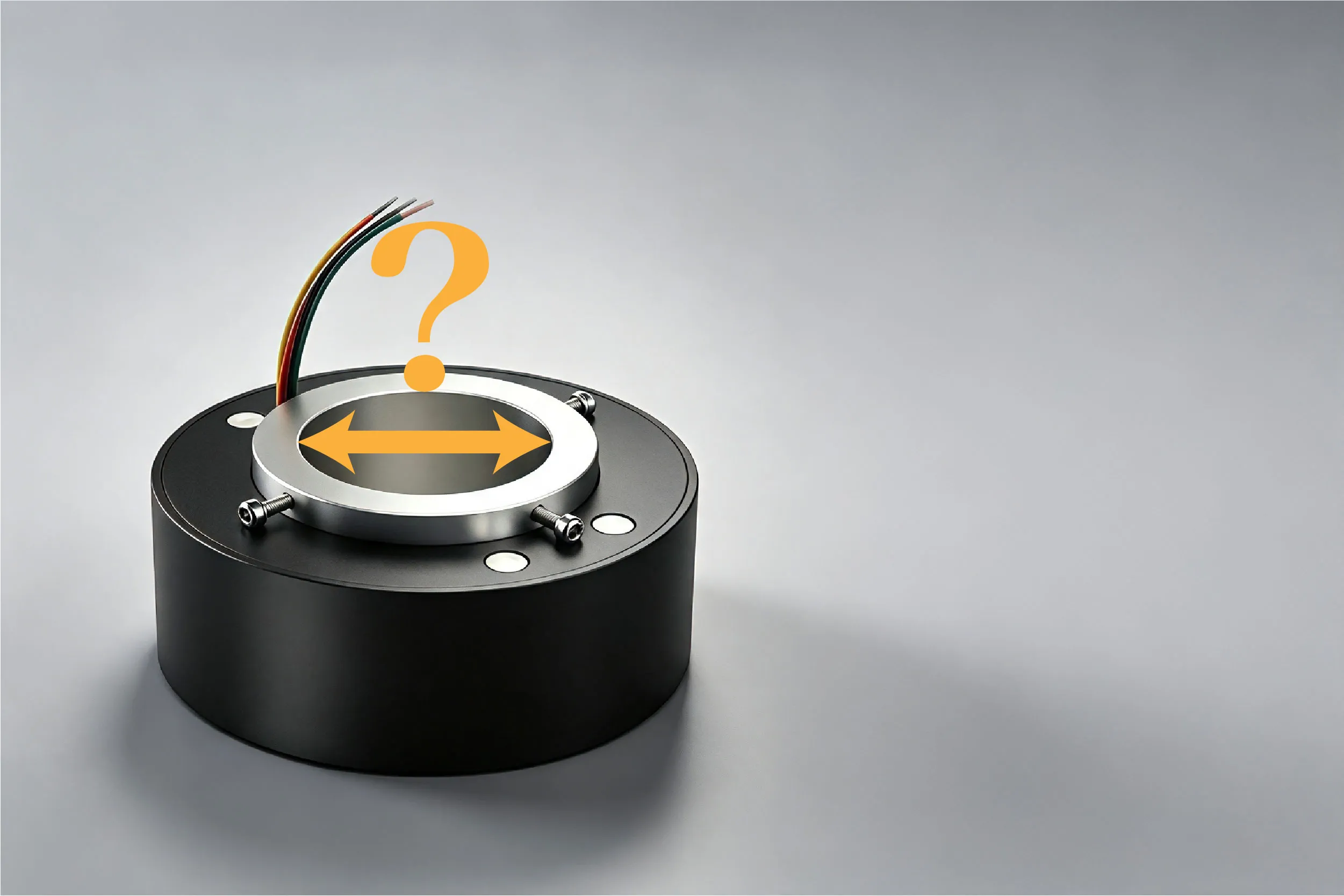
Bore diameter is one of those specification fields engineers fill in at the last minute, often with a comfortable margin over the largest element they expect to pass through the center. A costly habit that. If it is too small, the shaft or the cable bundle will not physically fit. If it gets too big, the outer diameter increases, as does the weight, machining complexity, and cost. Bore diameter is not a safety factor; it is a calculated output that cascades into every other dimension on the slip ring specification.
Why the Bore Diameter Decision Matters More Than You Think
The bore diameter determines the inner limit of the annular space within which the brush assemblies, ring stacks, insulation layers, and bearing races must all fit. And the larger the bore, the larger the outer diameter has to be.
It's Not Just a Hole, It's a Design Constraint
A 25.4 mm bore results in an outer diameter of roughly 86 mm. 100 mm bore gives about 185mm. That scaling is no coincidence: it is the fixed material depth the annular wall needs regardless of bore size. The wider bore pushes the wall out. It leads to a heavier, more rotationally inert assembly. It also cannot spin as fast, puts more centrifugal stress on the brush contacts, and takes up more room, which might disqualify the unit from the housing it was designed for. Engineers who treat bore diameter as a loose guess rather than a precise minimum learn these lessons later, when they are more difficult to undo.
The Cost and Lead Time Multiplier
Most manufacturers offer standard bore sizes such as 12.7 mm, 25.4 mm, 38.1 mm, 50 mm, 60 mm, 80 mm, and 100 mm at a price. However, if you select a bore size that falls between two standard steps, say 45 mm or 70 mm, you are now in the world of custom manufacturing. Costs rise, lead times increase, and supplier flexibility decreases. Engineers who oversize just a little without knowing where the standard steps end can push right past that point without realizing it and place a custom order for a unit that a standard bore would have covered.
What Actually Determines Your Minimum Required Bore Diameter
There are 4 types of pass-through elements with different sizing logic.
Rotating Shaft Pass Through
The bore must be larger than the shaft outside diameter by an amount sufficient to provide running clearance and to accommodate dynamic eccentricity. The standard practice adds 0.2-0.5 mm, depending on the installation method and the vibration environment. Shaft runout under load is significant here; undersized clearance in a dynamic system causes the shaft to contact the bore wall, and wear both surfaces, creating bearing stress the slip ring was not designed to carry. The typical starting points for that application tier are 25.4 mm and 38.1 mm bores, while compact servo systems and robotic joints usually have shafts in the 12-30 mm range.
Cable Bundle or Wire Harness
A cable bundle diameter is not a constant. It grows with every circuit added. The correct number to work from is the full bundled outer diameter, including insulation, shielding braid, and any strain relief sleeve, measured at assembly, not derived from individual conductor specifications. Bore routed cables also require a bend radius margin. When the routing path is curved, a bundle that fits the bore in a straight run can bind at the entry or exit, so clearance calculations must account for the routing geometry, not just the cross-sectional diameter.
Hydraulic or Pneumatic Lines
Hydraulic hose outer diameters can vary significantly depending on pressure rating and bore size. In heavy industrial or vehicle-mounted systems, the hose OD alone can drive bore requirements to 180 mm or more, before even considering fittings or protective sleeves. It is made worse by multiple parallel hoses - the calculation must be done on the bundled envelope of the grouped cross-section, not on the largest individual hose. The bore environment must also be compatible with the fluid temperature and pressure, as the electrical components in the annular space are affected by condensation or heat from hydraulic lines.
Hybrid Pass Through
In reality, many installations route shafts, cables, and fluid lines together. The bore must pass all the elements together, the composite envelope of all elements, not just the largest element. The sum of the cross-sections of a shaft with a cable layer around it and a hydraulic line placed next to it may be significantly larger than the cross-section of each component. This composite OD + clearance is the true minimum bore.
The Standard Bore Size Spectrum: Matching Application Tiers
The bore selection is more tractable when you map the application categories to the ranges they consistently fall into.
Bore Range | Typical Application Tier | Representative Use Case |
to the ranges they | Gimbal end-effector signal pass-through | |
12.7 mm – 25.4 mm | Servo robotics, automation joints | Robotic arm joint shaft + signal cabling |
38.1 mm – 60 mm | Mid-range industrial, packaging, gantries | Rotary table with pneumatic valve bank |
80 mm – 100 mm | Industrial turrets, radar pedestals | Pedestal yaw with hydraulic + power |
150 mm – 300 mm | Wind turbines, heavy machinery | Pitch control hub with hydraulic lines |
300 mm – 1,000 mm+ | CT scanners, large ring indexers | Medical gantry with patient table pass-through |
At the end, CT scanner slip rings have bore diameters of 2 meters or more. These are not standard catalog units but fully engineered systems in which the bore diameter is the dominant design driver, and the electrical transmission specification is derived from the remaining annular space. What actually has to go through the center, not how high above that it looks like a safe margin, determines the right tier for any application.
The Oversizing Trap: Why Bigger Is Not Safer
It is not conservative engineering to specify a larger bore than the application needs - it creates its own problems.
Mechanical and Structural Consequences
A larger bore means a larger outer diameter, which increases the moment of inertia of the rotating assembly. It causes additional centrifugal stress on the brush contacts and the ring stacks at higher speeds. The larger the bore diameter, the lower the maximum rated rotational speed, typically. It can conflict with the application's speed requirement and is not apparent until the slip ring specification is near final. Inertia also affects the accuracy of the dynamic positioning of the servo driven systems. The heavier the rotating mass, the more torque is required to accelerate and decelerate it.
Cost and Complexity at Scale
The larger the bore of the slip ring, the more raw material is needed; the higher the machining tolerances over a larger surface area, the more complex the assembly fixture; and, in many cases, the more auxiliary support structure is needed during installation. These factors combine to yield a considerable cost premium over the next-smallest standard bore size. That larger bore was not mechanically necessary, so the premium is wasted.
Signal Integrity Risks with Enlarged Housings
The larger outer diameter increases the physical distance between the ring tracks and the housing wall, which can make the shielding and isolation architecture more difficult. The physical size of the unshielded power and signal circuits also increases, adding to the risk of EMI coupling across the annular section. It is particularly true in designs where power and feedback signals share the same ring stack with inadequate isolation between rings.
How to Calculate Your Bore Diameter
A systematic four-step process produces a defensible bore diameter, not an estimate.
Inventory Every Element Passing Through the Center
List all shafts, cable bundles, hydraulic hoses, pneumatic tubes, structural rods, and support columns that need to go through the bore. It is the most often skipped step and the one that most often causes undersizing mistakes found during assembly.
Compute The Composite Envelope
Check if the pass-through elements are concentric or parallel. For a concentric arrangement, shaft with cables wound around it, the composite OD is the shaft OD plus twice the cable layer thickness. Calculate the bounding envelope of the grouped cross section for the bundles in parallel. Neither calculation is equal to the largest single element.
Request Clearance
Leave 0.2 to 0.5 mm radial clearance for the shaft bearing. More may be required for cable bundles and hydraulic fittings that require in-line access during maintenance. Compare the resulting minimum bore ID with the vibration tolerance of the application and installation geometry.
Size Up to Next Standard Size
Then you round the calculated minimum bore ID to the nearest standard step: 12.7, 25.4, 38.1, 50, 60, 80 or 100 mm. A custom bore is only justified where a standard size will not fit within the composite envelope without adding an outer diameter that can only accommodate.
How Bore Sizing Varies Across Industries
The sizing logic is consistent across industries, but the main constraint varies with the application.
Robotics and Industrial Automation
Compact servo joints are typically sized with bores from 12 to 38 mm. End of arm tooling with combined pneumatic and signal pass-through can be as large as 50 or 60 mm. The limiting constraint is the outer diameter: a slip ring that expands the kinematic envelope of the arm decreases positioning reach and increases collision risk in tight workspaces.
CT Scanners and Medical Imaging
CT gantries must have sufficiently large bore diameters to allow the patient table to move continuously through the rotating assembly during scanning. They are amongst the largest through-bore slip rings, with bores ranging from several hundred millimeters to over 2 meters. Bore diameter is the key design driver in this application; electrical transmission capacity is specified in the annular space left by the bore size. The mechanics of CT scanners have evolved to require this geometry, as described in the Encyclopedia Britannica entry on medical imaging.
Wind Turbines
Hydraulic lines and power cables are routed from the fixed hub to the rotating blade root by pitch control systems. It is not just the bare hose outer diameters that the bore must accommodate; it must also accommodate fittings and protective sleeves. It has the effect that under-sizing at this stage leads to assembly problems that are costly to resolve on an installed turbine.
Radar and Defense Turrets
For pedestal-mounted radar systems, the margin for error is less than most other bore sizing applications. The slew rates at which these systems operate impose dynamic loads on brush contacts that increase with outer diameter and rotational inertia. Choosing a bore larger than what the cable and power routing truly needs is not a safety thing.
Conclusion
Bore diameter is a number that should come out of a calculation, not a guess. If you work out what really goes through the center, build the composite envelope, apply actual clearance values, then map to the nearest standard step, you get the smallest bore the application really needs. That figure minimizes the outer diameter, manages both cost and lead time, and avoids the inertia and structural penalties that an oversize bore quietly introduces. The easy way out is to go with a round number that feels safe and put the consequences on the assembly, the integration and eventually the service life.
NBG Innovations Group Pte.Ltd.
#13-13A, International Plaza, 10 Anson Road, Singapore (079903)


Navigation
 HomeSustainable
Product