


How to Select a CT Slip Ring: A Complete Engineering Guide
BY NBG
 2026-08-31
VIEWS: 1129

How to Select a CT Slip Ring: A Complete Engineering Guide
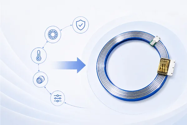
The CT slip ring is the electromechanical link that lets the scanner gantry keep turning while also sending high-voltage power to the X-ray tube and image data from the detector back to the computer that stays still. One of the biggest engineering challenges in CT design is getting a lot of image data across a rotating boundary without adding any errors. This guide covers the six technical factors used to choose a CT slip ring. It ends with useful tips on how to evaluate a medical slip ring supplier.
Why the CT Slip Ring Is a Critical Design Choice
Before slip-ring technology became common, CT gantries had cable-wrap designs that allowed only limited rotation. When the slip ring was changed to continuous spinning, helical (spiral) scanning became possible and is now the standard in clinical practice.
During operation, the slip ring has to send three things at the same time: high-voltage power to the X-ray tube, low-speed control and bus signals, and high-bandwidth detector image data back to the stationary side. Without careful separation, these three areas cannot use the same contact technology because their electrical properties are so different.
If you don't choose the right parts in any of these areas, you could end up with bad images, bit errors in detection data, faster brush wear, EMC violations, and costly service calls for hospital equipment that is already set up. The sections that follow discuss each selection criterion in the order of how it affects the design.
1. Data Transmission Requirements
When choosing a CT slip ring, the data transmission requirements in this scenario require the following considerations.
Data Rate
Today's multi-slice and dual-source CT scanners produce huge amounts of detector data that would not have been possible ten years ago. Throughput requirements increase as slice count and sampling rate increase. Mainstream capacitive-coupled contactless architectures typically operate at data rates of around 10 Gbit/s.
Newer contactless designs are sold at much higher speeds; one major supplier claims speeds of up to 340 Gbit/s, but these numbers should be checked against independent test data and relevant standards before they are used in a specification.
Signal Type
The slip ring needs to be able to handle three different types of signals at the same time. Power rings bring high-voltage and high-current electricity to the X-ray tube. Lower-speed command and status signals are sent between stationary electronics and rotating equipment through control and bus channels. Image data from detectors is sent over high-speed serial channels.
Different types of conductors, insulation, shielding, and contact materials are needed for each domain. When you mix them without ensuring they are electrically separate, crosstalk and noise are introduced that lower picture quality.
Bandwidth & Transmission Method (Contact vs. Contactless)
The most important technical decision in the process is between brush-contact and contactless coupling. Power rings and control signals with lower speeds work well with sliding brush contacts. To send fast image data across a rotating interface, you usually need a method that doesn't involve touching it.
2. Rotation Speed Requirements
The time of gantry movement directly affects the time resolution. Imaging of cardiac structures is better with faster rotation, and motion artifacts are reduced in patients who cannot remain still. Early slip-ring gantries could turn fully twice or three times in two to three seconds.
Modern systems can turn 360° in about 0.28 to 0.35 seconds, and air-bearing test platforms have shown that they can turn in about 0.20 seconds, which is about 300 rpm.
When you describe a slip ring, you should list both the maximum RPM and the continuous duty-cycle RPM. In clinical settings, the workload rarely matches the peak speed. When high spinning rates are kept up for a long time, brush wear speeds up, dynamic contact resistance rises, and centrifugal loading puts stress on the rotor assembly.
The rated bearing life, contact resistance stability, and mechanical balance of the slip ring must all be checked at the actual operating speed profile, not just a set number.
3. Number of Electrical Channels
Each ring-and-brush pair, also known as a coupled contactless channel, is its own separate electrical circuit. Before you say how many channels you want, you should list all the wires that need to cross the spinning interface. These include three-phase power lines, protective earth and neutral, control and bus signal pairs, and high-speed data channels.
Give each power ring a current rating and add a thermal derating margin. This is because high temperatures inside a sealed gantry enclosure lower the safe continuous current rating.
The best thing to do is to add 15–20% extra lines on top of what is needed by design. Adding more sensor channels, making changes to the hardware in the future, or the need for redundancy almost always means that more wires are needed than were planned in the original design.
If the channel count isn't specified correctly, the whole slip ring assembly has to be replaced instead of just adding a few channels, which is a much more expensive option for an already installed system.
In CT applications, signal rings commonly use high-silver carbon brushes, while power rings use low-silver carbon brushes. This should be discussed with the supplier early in the planning process.
4. Mechanical Dimensions & Integration
CT slip rings are large-diameter, through-bore devices. The internal bore must clear the patient aperture and the gantry's rotating frame, with bores on some systems reaching approximately one meter or more. An electrically correct slip ring that does not fit the gantry is useless, so mechanical integration must be verified at the earliest possible design stage.
Bore & Envelope:
Check the gantry drawings with tolerances, not nominal dimensions, to make sure the inner diameter, outer diameter, axial length, and mounting-flange interface are correct.
Fit & Alignment:
Total indicated runout (TIR) and concentricity directly affect contact noise. Tolerances for the shaft and flange must be given; misalignment leads to early wear and higher electrical noise.
Contact Technology:
For low-current signal rings where noise floor is important, gold-on-gold fiber-brush contacts are best. Most power bands have brushes made of silver-graphite or carbon-composite. Make sure that the gantry's maintenance access paths work with the cable exit routing, connector envelope, and service clearance.
5. Reliability & Regulatory Compliance
CT slip rings must meet regulatory compliance and should be reliable enough; some standards and regulatory protocols to follow are as follows:
Service Life & Wear
In hospitals, CT scanners are used almost all the time. Measure the number of rated rotations and operating hours, not just the number of years, and compare them with the expected clinical duty cycle. When gantry access is limited, choose contact technologies that don't need much upkeep or only need to be inspected every so often.
A slip ring with unstable or rising contact resistance will slowly lower image quality over time before it completely fails. This means that low and stable resistance is both an electrical and a reliability measure.
EMC & Safety Standards
The IEC 60601 series sets standards for medical electrical equipment. IEC 60601-1 covers basic safety and performance requirements, and IEC 60601-1-2 covers electromagnetic compatibility. Because the slip ring can be a source of noise in a safety-critical imaging system, suppliers should be able to show proof of EMC validation in real-world operating conditions, not just clean-room lab conditions.
Before adding certain clause language to a procurement specification, check the main IEC documents to make sure they match the relevant edition, any regional variations, and any relevant collateral standards.
6. Customization Capability
Standard catalog slip rings will rarely work with a CT gantry. Most of the time, engineering is needed to make the platform's bore diameter, channel count and mix, voltage and current ratings, data-coupling architecture, and mechanical mounting interface. Not only should you look at how quickly a provider can deliver a catalog item, but also how well they can co-engineer the solution, which could include prototyping, shock and vibration qualification, and accelerated life testing.
Choosing a Medical Slip Ring Supplier
When choosing a supplier, you should look for one with a history of working with CT and medical imaging, its own research and development and test labs, an ISO 13485-compliant quality system, clear data on reliability and lifecycle, and a track record of long-term supply stability for both new platforms and service for existing ones.
Selection Checklist & Conclusion
Before finalizing a CT slip ring, confirm each of the following:
● Data rate, BER requirements, and transmission method (contact vs. contactless)
● Maximum and continuous RPM at clinical duty cycle
● Channel count with 15–20% spare margin, current ratings, and derating
● Bore, outer envelope, mounting interface, and service clearance
● Rated service life in revolutions and hours; contact resistance stability
● IEC 60601-1 and IEC 60601-1-2 compliance documentation
IEC 60601-1 和 IEC 60601-1-2
● Supplier's co-engineering, validation, and long-term support capability
The choice of CT slip ring is made at the systems level, taking into account imaging performance, mechanical interaction, and regulatory compliance. It should be done early on in the gantry development process and with the help of a supplier with direct knowledge in medical imaging applications.
NBG Innovations Group Pte.Ltd.
#13-13A, International Plaza, 10 Anson Road, Singapore (079903)


Navigation
 HomeSustainable
Product