


Rotating Shafts, Pneumatic Tubes and Fiber Lines: How to Use the Center Bore Efficiently
BY NBG
 2026-07-16
VIEWS: 1861

Rotating Shafts, Pneumatic Tubes and Fiber Lines: How to Use the Center Bore Efficiently
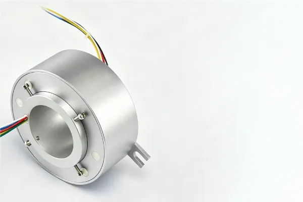
Rotating assemblies that must simultaneously carry mechanical torque, pneumatic pressure, and high-bandwidth optical or electrical signals face a fundamental packaging problem: no cable tangle, no winding limits, minimal axial footprint, all at once. It is enabled by the hollow center of the through-bore slip ring, and not just as a mounting convenience. All bore-diameter millimeters have conflicting requirements. It’s knowing how to sequence, size, and allocate those claims that determines whether a rotating assembly is compact and integrated or bloated and failure-prone.
Anatomy of the Center Bore and What the Hollow Actually Is
The center bore is an active design resource. Every decision that follows is limited by its structure, by what it can physically accommodate.
The Through-Bore Slip Ring vs. Solid-Center Designs
A slip ring with a through bore is an electromechanical device with a hollow center channel that allows cables, tubing, or shafts to pass axially while maintaining continuous 360-degree electrical contact with the outer rings. In capsule and pancake slip ring designs, there is no useful central passage; the rotating interface occupies the entire cross-section. The through-bore design allows for the routing of layered media. The conductive rings are concentrically disposed about the bore. Brushes make sliding contact with the rings, not breaking the passageway.
What Can Occupy the Center
In practice, there are three basic types of bore occupants: a rotating mechanical shaft such as a concentric drive shaft, gear shaft, or spindle; pneumatic or hydraulic tubing that supplies air, vacuum, or coolant through a rotary union; and fiber optic lines or signal cables routed on-axis through a fiber optic rotary joint or run coaxially through the bore. Layered configurations are common; they are not mutually exclusive, but each occupant must compete for radial space, and that competition must be resolved before a slip ring is specified.
The Three Media Types and Their Boring Demands
Different media types have distinct physical constraints, and treating them as interchangeable in the bore layout will lead to installation problems.
Mechanical Shafts with The Structural Backbone
A typical application of the through-bore architecture is the mounting of concentric shafts. The slip ring is mounted on an existing drive shaft, so no additional mechanical support is needed; the axial length is reduced, and no auxiliary bracket is needed. The rule for clearance is simple: the bore diameter must be larger than the shaft’s outer diameter, typically by 2 to 5 mm, depending on the installation method and the required concentricity. In shaft-mounted designs, the minimum bore size is set early in the design process. All other media must be accommodated within the remaining annular space or moved outside the design. This architecture is especially advantageous for retrofit applications, where through-bore units can be mounted on existing shafts without redesigning the surrounding structures.
Pneumatic and Hydraulic Lines with Pressure, Sealing, and Temperature
When the pneumatic or hydraulic media must pass through the rotation interface, a rotary union is incorporated coaxially into the bore or as a combined unit with the slip ring body. Design parameters include the working pressure rating, the number of circuits, the media temperature range, and the seal material compatibility. NBR, PTFE, and Viton each suit different media and temperature profiles. Steam or high-temperature lines may require a heat-insulating sleeve inside the bore. Cold-environment applications require seal materials rated for low-temperature flexibility. Combined slip ring and pneumatic rotary union assemblies save total axial length compared to stacking separate units in series, an important consideration when envelope space is limited.
Fiber Optic Lines with On-Axis vs. Off-Axis FORJ Architecture
An on-axis fiber-optic rotary joint has the optical signal path along its central rotational axis. The bore itself serves as the optical interface, with no center space left for shafts or tubing; this is an optical-first architecture. The fiber optic interface is radially offset in an off-axis through-bore configuration, leaving the center bore free for mechanical or fluidic applications. The trade-off is optical performance: on-axis joints tend to have lower insertion loss and cleaner alignment. Off-axis designs sacrifice some optical performance for a free bore. Applications that require a fiber-optic gearbox and a clear bore, including CT scanners, radar systems, and marine propulsion, are engineered with the off-axis configuration as the standard. Wikipedia has a good overview of fiber-optic components. In rotary optical joints, the insertion loss is primarily a function of the precision of the rotary interface alignment.
Bore Sizing with The Allocation Logic Engineers Must Follow
Bore sizing is not a lookup; it is a calculation that must account for everything competing for the same cross-sectional space.
Establishing the Minimum Required Inner Diameter
Start with a list of all the items that must physically pass through the bore: shaft OD, cable bundle OD, tubing OD, and any required protective conduit. Provide for installation clearance, normally 2 to 5 mm for shafts, larger for tube bundles that require angular flexibility or must accommodate thermal expansion. The resulting minimum bore diameter is a non-negotiable floor for slip-ring selection.
The Priority Hierarchy When Space Is Constrained
When all three media types compete for the same bore, a functional priority framework avoids under-specification. The mechanical shaft is the number one priority because you can’t negotiate structural continuity away”. Second are pneumatic and hydraulic lines, as high-pressure sealing is difficult to relocate externally once a system is packaged. Fiber-optic and signal cables provide the most flexibility; shielded bundles can often be run on the outside or in split conduit if bore space is exhausted. The responsible thing to do is to recognize that the bore cannot accommodate all three and plan to route the lower-priority media externally. External trunking is your fallback.
Oversizing vs. Undersizing
Assembly errors, concentricity problems, and seal damage during installation occur when the size is too small. Excessive oversizing increases the slip ring’s outer diameter because the ring and brush stacks must be outside the bore, thereby increasing the assembly’s mass and envelope. Both options have associated costs, so the bore occupancy map must be completed before procurement.
Integration Configurations in Real Systems
Theory corresponds to concrete system architectures. The implications of bore allocation decisions are illustrated for three application areas under realistic engineering constraints.
Robotics and Industrial Automation
Multi-axis robot wrists and rotary end effectors require simultaneous power, encoder signals, pneumatic gripper actuation, and more, along with increasing Ethernet or fieldbus communication. The slip rings are through-bore, so the robot axis shaft can pass right through the center of the ring stack and into an integrated rotary union that handles electrical and pneumatic circuits, all in a single compact housing. Industrial Ethernet protocols such as EtherCAT, PROFINET, and EtherNet/IP are available in hollow-shaft variants, removing the need for external communication trunking on articulated arms.
Medical Imaging with CT Scanners
The canonical example of complex bore usage is the CT scanner. The gantry rotation interface must simultaneously carry high-voltage power, data signals, and, in some configurations, coolant lines for X-ray tube thermal management. Through-bore fiber-optic rotary joint configurations are used in slip-ring CT systems, where the bore is left open for structural gantry components and rotating frame hardware. The slip-ring CT design enabled continuous rotation of the gantry and, with the advent of helical scanning, defined modern diagnostic imaging capability, according to the National Institute of Biomedical Imaging and Bioengineering.
Wind Turbines and Packaging Machinery
The wind turbine pitch control systems are designed so that the blade pitch shaft passes through the bore, and the ring stack carries the power and control signals for the pitch actuators. Packaging machinery that is carousel-based combines rotary assemblies with pneumatic suction-cup actuation, through-bore designs provide electrical pathways, while air delivery passes through the integrated center union.
Common Design Pitfalls and How to Avoid Them
Most failed integrations are the result of the wrong early decisions made with incomplete information, here’s where those decisions fail and how to avoid them before they go to procurement.
Pitfall | Root Cause | Correction |
Mismatched bore diameter at procurement | Specifying bore ID based only on shaft OD, ignoring secondary media | Complete a bore occupancy map before issuing the specification |
Thermal incompatibility between bore media | Hot pneumatic lines are routed adjacent to fiber or signal cables | Use thermal isolation sleeves or maintain radial separation in the bore layout |
Excessive axial length from stacked units | Specifying a separate slip ring, rotary union, and FORJ in series | Evaluate combined hybrid units against total system envelope requirements |
Defaulting to custom when standard suffices | Assuming standard bore sizes cannot meet requirements without checking | Review standard bore size offerings first; escalate to custom only when performance is genuinely compromised |
Selection and Specification Checklist
You’ll avoid the most common procurement errors when specifying any through-bore assemblies by using a structured checklist. First, list the shaft OD, tubing OD, and cable bundle OD, along with their corresponding clearance allowances. Then find the minimum bore OD. Specify electrical circuit requirements (number of circuits, current and voltage ratings, signal types). Pneumatic and hydraulic parameters: number of circuits, working pressure, media type, temperature range, seal material. Optical requirements for determining FORJ (on-axis or off-axis), the number of channels, fiber type, and the maximum acceptable insertion loss shall be defined. Check the RMP range and if speed affects brush wear, seal integrity, or optics alignment. Choose environmental rating (IP class, operating temperature, vibration resistance). Check standard bore sizes before going custom. Most bore requirements are within the standard offerings when the occupancy map is done correctly.
Conclusion — Design the Bore Before You Design Around It
When the electrical rings are laid out, the center bore of a through-bore slip ring is not wasted space. It is an active design resource that must be allocated deliberately, mapped before the slip ring is specified, and treated as a first-order design document on a par with the electrical circuit list and the mechanical envelope drawing. The best and most compact rotating assemblies are always those in which bore occupancy is addressed at the concept stage rather than fixed during integration.
NBG Innovations Group Pte.Ltd.
#13-13A, International Plaza, 10 Anson Road, Singapore (079903)


Navigation
 HomeSustainable
Product