


Design Challenges in Miniature Slip Rings
BY NBG
 2026-07-13
VIEWS: 1015

Design Challenges in Miniature Slip Rings
Miniature slip rings are smaller than a fingertip, yet they must transmit power, data, and control signals through a full 360° rotation. They work in environments where failure is not an option, such as UAVs, surgical robots, CT scanners, gimbal systems, and small-scale industrial automation. The global market for small slip rings is expected to grow at a 7.4% annual rate, reaching $589 million by 2034, up from $360 million in 2025. The problems that arise in engineering as devices get smaller, like wear on contacts, heat dissipation, signal integrity, and precision in manufacturing, don't shrink with the device. In many ways, they become much harder to solve.
The Miniaturization Imperative and Why Sub 16mm Form Factors Are Now Standard
It's not enough to make a slip ring smaller; you have to do more than that. Every limit at the standard scale becomes tighter, and new failure modes appear that don't occur in larger assemblies.
What is a Miniature Slip Ring
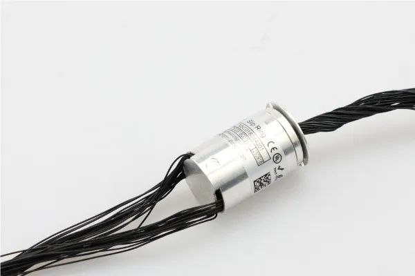
Capsule and micro slip rings usually have an outer diameter of 6-22mm, and the brush wires can be as fine as 0.07–0.5 mm. They use lower ring pitch spacing, tighter inter-circuit clearances, lower contact force budgets, and much lower heat dissipation volume than regular slip rings. Different installation geometries require different form factors, such as capsule (solid shaft), miniature through-bore, and pancake.
Application Drivers Pushing Miniaturization
Because of the weight and size of the payload, UAV and drone gimbal designs have outer diameters of less than 16 mm. Small multi-circuit rotary interfaces that are IP67 or higher sealed are needed for medical imaging systems, such as CT scanner gantries and surgical robotic wrists. Autonomous mobile robots and industrial robotics limit the bore diameter at articulated joints without reducing the number of circuits. In these fields, miniaturization is not a trend; it is the norm for design.
Contact Material and Wear and The Core Engineering
The contact interface is where the physics of making things smaller really hits home. The way material choice, brush shape, and contact force interact is not captured by standard-scale design rules.
The Role of Contact Material in Miniature Performance
Gold-alloy contacts are the best choice for low-voltage signal circuits because they don't oxidize quickly, have stable contact resistance (≤0.01 Ω), and generate little electrical noise. Gold alloy contacts, on the other hand, only last about 40% as long in rings less than 5 mm in diameter as they do in larger rings. It is because the brush pressure is higher per unit area, and there is less ring surface to spread out the wear. The main options are families of precious metal alloys, such as Palladium 7, Palladium 25, and Nymoro G. Each has its own advantages and disadvantages regarding price and durability.
Brush Spring Force
The force exerted by the brush when it touches the capsule-type rings is about 10–15 g. If there isn't enough force, the rings only touch sometimes. If there is too high, the ring grooves wear out faster, and the friction torque increases. In small rings, the spring part needs to be smaller while maintaining stable pressure and calibration throughout the product's life. Multi-fiber or polyfilament wire brushes touch at multiple points, reducing resistance and spreading wear more evenly. In small enclosures, wear debris is more dangerous because the particles don't have as much room to spread out and can get into nearby ring channels.
Noble Metal Investment
Gold-to-gold contact pairs are worth the extra cost for UAV payloads and surgical instruments where unscheduled maintenance isn't possible. Carbon-graphite brushes are cheap for power channels in larger hybrid designs, but they produce too much debris for sealed miniature enclosures.
Table: Contact Material Options for Miniature Slip Rings
Material | Resistance Target | Strength |
Gold-on-gold | ≤0.01 Ω | Lowest noise, no oxidation |
Paliney 7 / 25 | ≤0.01 Ω | Harder, better wear distribution |
Neyoro G alloy | ≤0.01 Ω | Tarnish resistance |
Carbon-graphite | Application dependent | Cost-effective for power channels |
Thermal Management for Dissipating Heat in a Compressed Envelope
Heat is one of the hardest things to see and the most harmful things to deal with when designing a miniature slip ring.
The Heat Problem at Reduced Scale
When the same amount of electricity is used, miniature slip rings are 15–20°C hotter than regular-sized ones. It is because they don't have as much surface area to let heat out. There are places where heat can escape, like resistive losses at the brush-ring interface, friction in the bearings, and dielectric losses in the insulation. High temperatures speed up contact oxidation, reduce bearing lubricant viscosity, and lower insulation resistance. All of these things cause wear and signal degradation simultaneously.
Design Strategies for Thermal Control
Aluminum alloy housings are better than plastic ones because they transfer heat away from the contact zone more effectively. If the dynamic contact resistance variation stays below 9 mΩ, it stops resistive heating at the interface. Hybrid ceramic bearings produce less frictional heat than steel-on-steel bearings, which is important for high-speed designs that can go up to 2000RPM.
Signal Integrity and EMI for Protecting Data Circuits in Compact Multi-Channel Designs
The electrical performance of small multi-channel assemblies depends on how well the parts fit together and on the materials used.
Crosstalk and Channel Isolation
When the spacing between ring pitches is smaller, the capacitive and inductive coupling between nearby channels becomes stronger. It is what makes crosstalk happen. This worsens the feedback from the encoder, the Ethernet data links, and the analog sensor channels. Design responses include the exact thickness of the inter-ring insulation, separate ground ring channels between signal circuits, and shielded twisted-pair lead arrangements from the ring stack to the ends of the connectors.
EMI Emission and Susceptibility
Even a tiny arc from a brief loss of brush contact emits RF energy that disrupts nearby wireless systems. It is very important for UAV payloads and surgical robotic systems. Conductive housings create a Faraday-like enclosure that keeps RF emissions from getting out and outside interference from entering. For applications close to an MRI, the housing materials must not attract magnets.
High Speed Data Transmission Considerations
Controlled characteristic impedance, usually 50 Ω or 100 Ω differential, is required for industrial Ethernet speeds up to 1 Gbit/s and high-definition video speeds up to 3 GHz. It means that the ring geometry and the dielectric properties of the insulation must be made to tighter tolerances. It is necessary to check the insulation resistance between channels at ≥500 MΩ throughout the operational life, even in the presence of humidity and vibration, as would be encountered in the field.
Precision Manufacturing Tolerances and Where Physics Meets the Factory Floor
When manufacturing differences are small, they can cause major problems in a larger assembly.
Tolerances That Cannot Be Relaxed
A precision miniature slip ring should have a ring concentricity of 0.01 mm. Errors greater than 0.03 mm result in brush bounce, sporadic contact, and expedited asymmetric wear. The dimensions of the ring groove profile and the surface finish determine how evenly the wire brush sits, which directly affects the stability of dynamic contact resistance. Using vacuum-cast epoxy processes with controlled curing temperature and chemistry, insulation between ring channels must have a resistance of at least 500 MΩ.
Manufacturing Defect Rates and Quality Assurance
The average defect rate for miniaturized component production is 3–5%, which is much higher than the average for standard slip rings. Standard validation involves testing dynamic contact resistance over a full 360° rotation, testing insulation resistance between all channel pairs, and running life tests for 21 days at rated speed. To ensure consistent quality at this level, CNC wire forming, precision stamping, and CMM inspection are the minimum skills needed.
Application Specific Design Constraints with No Universal Solution
There is no one miniature slip ring design that works for every use. Each vertical has rules that are more important than general best practices.
UAV and Gimbal Systems
The binding limits are an outer diameter of 16 mm or less, a low starting torque to stop gimbal drift, and vibration resistance across the entire flight envelope. Power, PWM or analog control, and digital data are all common circuit requirements. They all have to fit within the total system weight budget, which is measured in grams.
Medical and Surgical Devices
The materials used for housing and insulation must withstand autoclaving at 121–134°C, exposure to ETO gas, and chemical sterilization at the hospital level. IP67 or higher is the standard for ingress protection. You can't use standard housing and bearing options near MRI machines, as they must be made of materials that don't attract magnets.
Industrial Automation and Robotics
Articulated robot arm joints need through-bore versions so that wiring harnesses and pneumatic lines can go through the ring center. The most important costs over the life of a product are the cost of the contact material and the bearings, not the initial unit price. It is because the product will undergo hundreds of millions of revolutions.
Conclusion
Contact wear, thermal management, signal integrity, EMI control, and manufacturing precision are all related problems. Fixing one can often make another worse. People who work in systems engineering should know how to make small slip rings. Before the first design choice can be made, the application's operating conditions, circuit mix, environmental rating, and maintenance philosophy must all be set. The best way to ensure a small slip ring works well throughout its life is to invest in validated simulation and life testing early on.
NBG Innovations Group Pte.Ltd.
#13-13A, International Plaza, 10 Anson Road, Singapore (079903)


Navigation
 HomeSustainable
Product