


How Does a CT Scanner Slip Ring Work: Inside the Rotating Data Transmission System
BY NBG
 2026-08-13
VIEWS: 970

How Does a CT Scanner Slip Ring Work? Inside the Rotating Data Transmission System
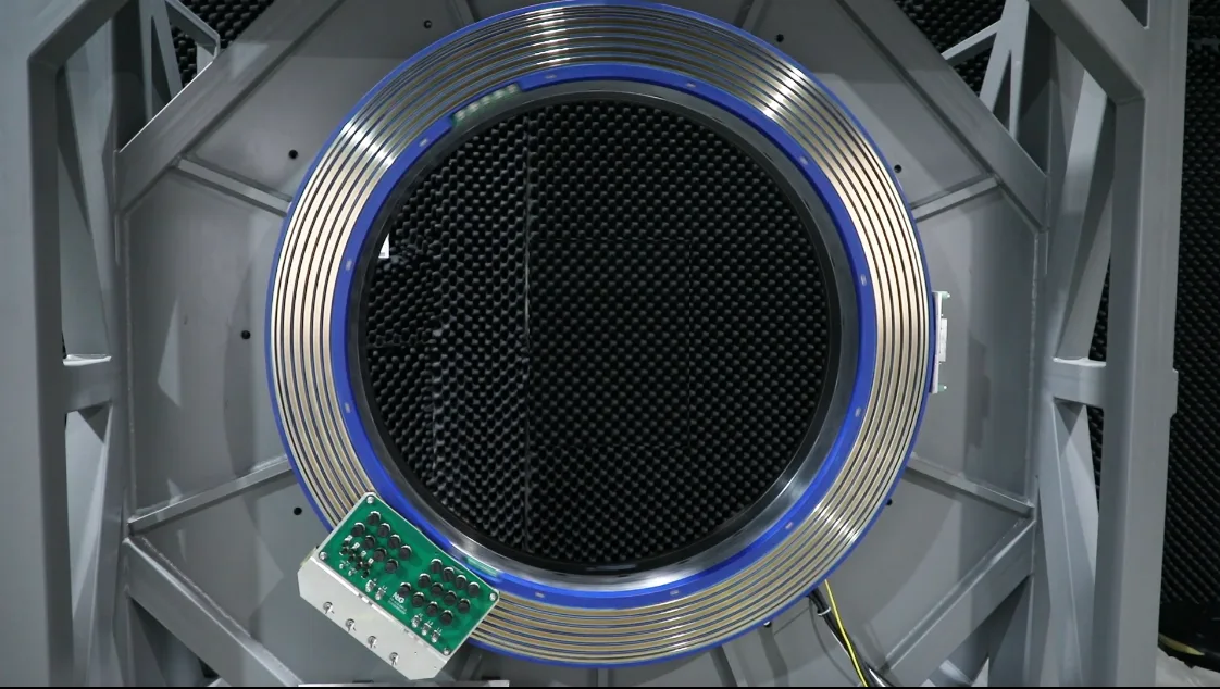
What makes a machine that spins at over 200 RPM keep kilowatts of power coming in and gigabits of image data going out without any wires getting tangled? The answer is the slip ring, the moving part of the gantry that lets it rotate continuously. To understand how the CT slip ring works, you have to look at the whole chain: the rotating gantry, the detectors that collect data, the technologies that send signals across the gap, and the engineering problems that get harder as data rates rise.
Why CT Scanners Need Slip Rings: The Continuous Rotation Problem?
Before slip rings, the way CT scanning worked put a hard limit on how quickly and constantly images could be taken. Modern helical CT and the clinical processes built around it were made possible by the shift from cable-tethered gantries to slip rings that enabled continuous rotation.
Cable Limitation of Early Scanners
In the first wave of CT scanners, fixed cables connected the moving parts to the frame that stayed still. The gantry had to stop, turn around, and unwind those cables after each full rotation so that the next scan could start. These stop-and-go cycles caused delays between scans and interrupted continuous data collection.
Slip Ring Solution
A slip ring on the rotor has conductive rings that are spaced out and stationary brushes that press against them. This is used instead of fixed wires. The gantry can spin in a single direction forever since it doesn't bend but instead slides against the wall. Power and messages keep going through the screen, even after the rotor has turned a few times.
Enabling Helical/Spiral CT
Around 1987, slip ring technology made its way into commercial CT machines. The gantry could spin nonstop, which let the patient table move through the hole at the same time, following a spiral path. This made it possible to image the whole organ in a single breath hold, added pitch as a design variable, and enabled multi-slice architectures.
CT Scanner Rotation Structure
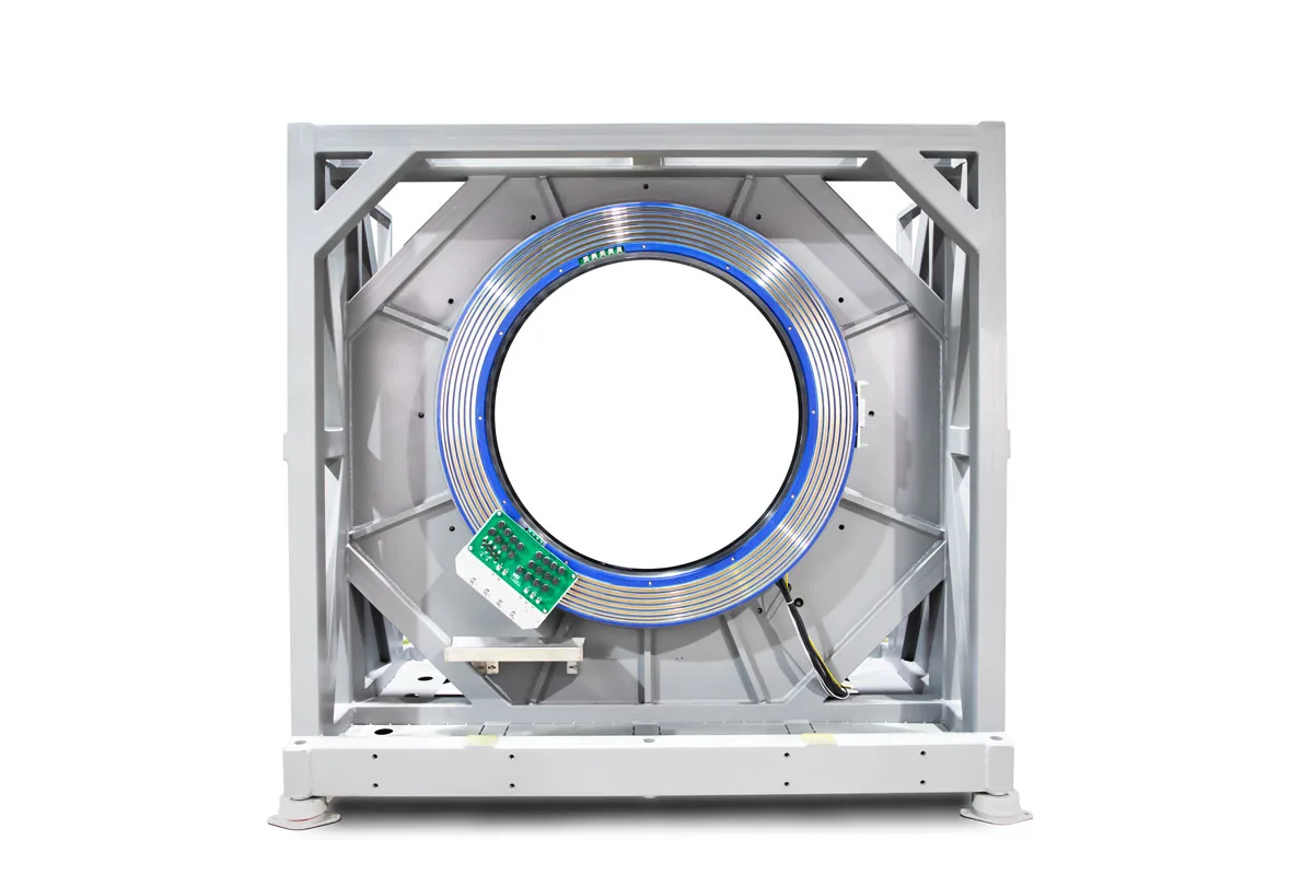
The rotating assembly of a CT scanner is a tightly linked system, which means that each part needs the others to work. To understand how power and data move across the rotating interface, you must first know how the gantry, tube, detectors, and slip ring assembly fit together.
Gantry
The imaging chain goes around the subject on a big ring that spins. This is called the gantry. Around its edges are the rotor and the slip ring assembly. In the middle is a hole that the patient goes through. These days, a full rotation takes much less than half a second.
X-ray Tube
For the X-ray tube to work, several kilowatts of high-voltage power must be sent across the rotating interface continuously. The gantry is pretty small, so the heat that is made during scans has to be taken away. This means that managing heat is a very important part of planning.
Detector System (DAS)
On the other side of the X-ray tube is a multi-row detector array that picks up the weakened X-ray beam after it goes through the patient. More simultaneous slices per rotation are possible with more detector rows. The Data Acquisition System (DAS) is right behind the detectors. It turns analog signals into digital ones and packages them so they can be sent across the rotating interface.
Slip Ring Assembly
The slip ring assembly is typically about one meter in diameter, sized to surround the patient bore while accommodating power rings, data channels, and control-signal channels in concentric bands. It must maintain precise concentricity and reliable electrical contact over years of continuous clinical use.
CT Slip Ring Working Principle: Power + Data
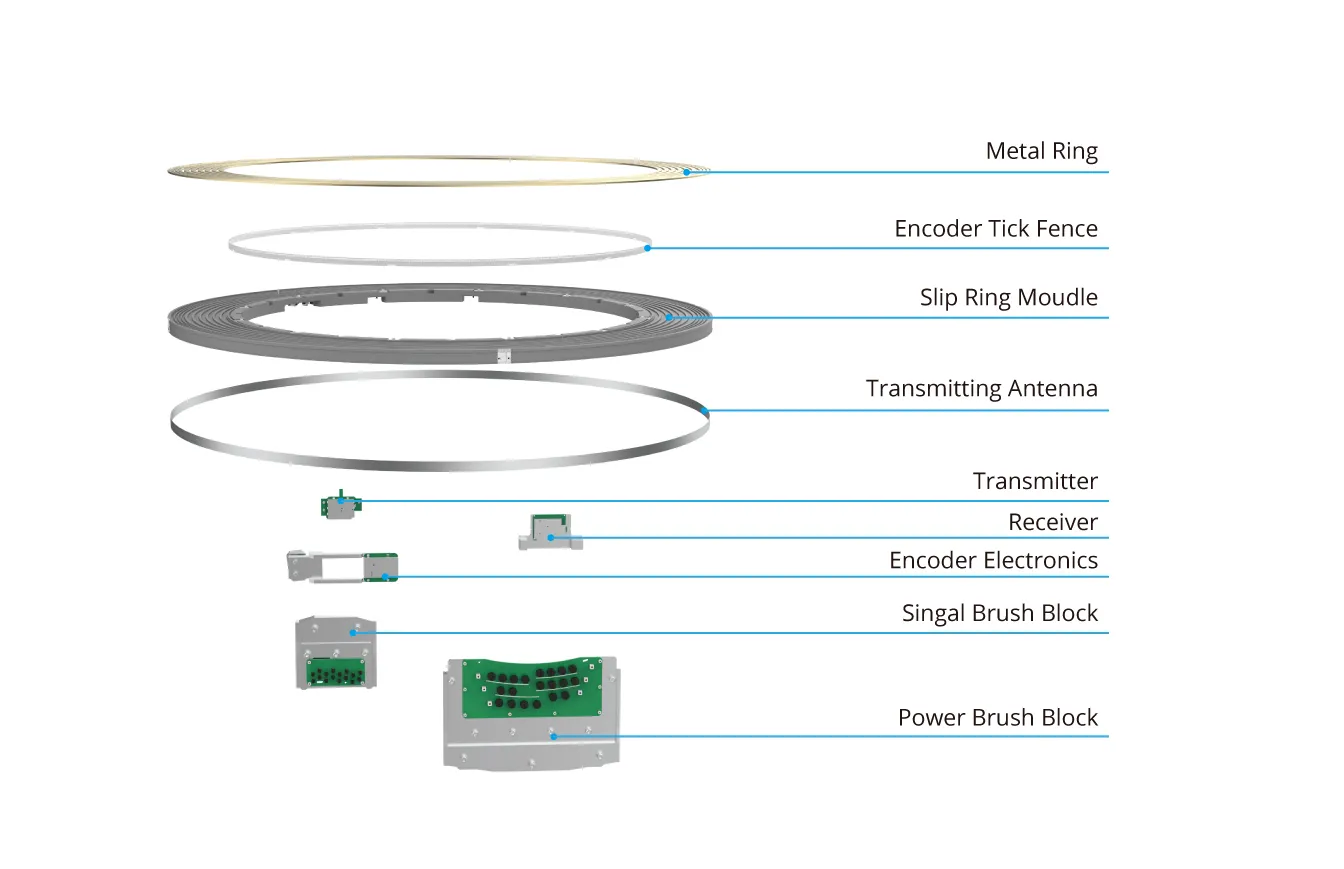
CT slip ring working mechanism is as follows:
Power Transmission via Sliding Contacts
For power to flow, conductive rings on the rotor must touch stationary brushes on the stator. Fiber-brush technology uses groups of very fine metallic filaments to spread the contact load over thousands of spots. This lowers wear and allows power transfer at kilowatt levels at high rotational speeds.
Two Distinct Jobs on One Interface
The slip ring must simultaneously handle two transmission paths in opposite directions at the same rotating interface. The stationary side sends control signals and supplies power to the rotating side, which in turn uses this to power the X-ray tube and other onboard equipment on the gantry. High-speed detector data, however, flows in only one direction from the rotating DAS to the stationary reconstruction system and does not involve bidirectional transmission. Ensuring that these two tasks proceed simultaneously without interfering with one another presents an extremely difficult challenge.
Why Can't Data Always Use the Same Path?
Power and low-rate signals work well with sliding contacts, but modern multi-row systems send more raw detector data than a brush-and-ring contact can easily handle. At gigabit-per-second speeds, changes in contact resistance and brush noise become major sources of bit mistakes. This is pushing the industry toward data paths without contacts.
Data Transmission Flow Inside the CT Scanner
Detector Array → Data Acquisition System (DAS) → CT Slip Ring (rotating interface) → Image Processing and Reconstruction System is the clear, straight line that the data goes through.
Step-by-Step
As the platform turns, the detector array records X-ray attenuation data at every angle. For sending, the DAS turns these signals into digital data and packs them into small packets. Through the slip ring arrangement, that packetized stream goes across the rotating interface. The reconstruction system on the stationary side gets it and figures out the cross-sectional images that are sent to the radiologist's desk.
Slip Ring as the Critical Bridge
The slip ring is the only electrical link between the rotating and non-rotating domains. Everything that comes from the detector has to go through it. There is no other path to take if bandwidth is not enough or signal integrity breaks at this crossing point. This means that picture quality will be directly affected.
Why High-Speed Data Transmission Is Critical
There are many reasons that make high-speed data transmission critical, and some of these are as follows:
Drivers of Data Growth
More raw data is being made every second because there are more detector rows, higher spatial resolution, thinner slices, faster rotation, photon-counting detectors, and multi-energy detectors.
Real Data Rates
In the past, multislice devices worked at speeds of several hundred megabits per second. The total output of modern systems often goes over 1 Gbit/s, and the output of the most advanced designs is measured in tens of gigabits per second. Specific numbers depend on the type of scanner and the company that makes it, so they should be checked against sources before being mentioned exactly.
Consequence for Design
At these speeds, an electrical data link that only contacts things becomes unstable. This forces designers to use capacitive and optical contactless links for the data channel.
Electrical vs. Capacitive vs. Optical Transmission Technology
No single transmission method can meet all the needs of a modern CT slip ring. Power transfer, control signals, and high-speed detector data all need different amounts of bandwidth, reliability, and noise tolerance. This is why three different methods have come up and are being used together more and more.
Contact Electrical Slip Rings
For power transfer and slower signals, brush-and-ring contacts are still the norm. They are easy to build and can handle large currents, but their contact resistance changes make them less useful for multi-gigabit data lines.
Capacitive (Near-Field) Contactless Links
A ring of differential transmitting antennas encircles the outer periphery of the rotor, and the receiver on the stationary side is coupled to it via capacitive coupling,without any mechanical touch. This method allows for high-frequency data flow that doesn't wear out and isn't affected by the changes in mechanical properties that happen with brush contacts.
Optical Data Channels / Fiber Optic Rotary Joints
The optical data channel employs free-space optical coupling: on the rotating side. a laser driver modulates the high-speed serial data output by the DAS into an optical signal. which is transmitted via a optical Fiber to a collimator that shapes it into a parallel beam. this beam crosses the air gap and is directed toward the stationary side. On the stationary side. a collimator refocuses the beam into an optical fiber. where a photodetector converts it back into an electrical signal and feeds it into the reconstruction system. The entire link has no mechanical contact whatsoever. This method also supports high-speed data transmission at the Gbps level. it is free from friction and wear, is inherently immune to electromagnetic interference, and provides complete electrical isolation.
Hybrid Assemblies
Most current CT slip rings use more than one type of technology. For power, they use electrical rings and brushes, and for data, they use capacitive or optical channels. Because of the gantry's limited room, this lets each technology do what it does best.
Engineering Challenges
The basic sliding-contact idea doesn't show how hard it is to make a slip ring that works with a clinical CT scanner. High rotational speeds, kilowatt-level power, multi-gigabit data rates, and a confined gantry environment all create a set of engineering problems that must be solved at the same time.
Signal Integrity
To keep gigabit-rate signals clean across a constantly changing gap, you need to match impedance, use error-correction coding, and pack the signals into packets that can be sent again. Each one adds extra work that needs to be weighed against the available speed.
Electromagnetic Interference (EMI)
The high-speed data channels and the high-voltage X-ray power path are both housed in the same small unit. If there isn't enough shielding, switching noise from the power electronics can mess up the data stream and add artifacts to the images.
Electrical Noise & Contact Wear
In designs that use contacts, brush wear causes dirt to form, raising contact resistance and adding noise. Addressing this over the years is a major maintenance issue and one of the best reasons to switch the data path to wireless technology.
Mechanical Precision
A ring with a diameter of one meter that spins at 200 RPM must stay perfectly straight and centered. Runout, vibration, and thermal expansion can all hurt contact quality and optical alignment. Also, the X-ray tube and power electronics produce heat in a place that doesn't have many ways to cool them down.
Conclusion
The CT slip ring is the spinning bridge that allows the gantry to rotate continuously. It sends kilowatt-level power to the X-ray tube and high-speed detector data back to the reconstruction system.
CT slip rings used to be just brush-and-ring contacts, but as data rates have increased, they've evolved into hybrid assemblies that combine electrical, capacitive, and optical channels. This change builds on the slip ring idea instead of replacing it, meeting needs that the original sliding contact design was not made to meet. Fiber-optic rotary joints, hybrid slip-ring design, and capacitive couplers for rotating systems are related topics you might want to learn more about.
NBG Innovations Group Pte.Ltd.
#13-13A, International Plaza, 10 Anson Road, Singapore (079903)


Navigation
 HomeSustainable
Product