


What Is a CT Slip Ring: Complete Guide for Medical Imaging Systems
BY NBG
 2026-08-10
VIEWS: 1690

What Is a CT Slip Ring? Complete Guide for Medical Imaging Systems
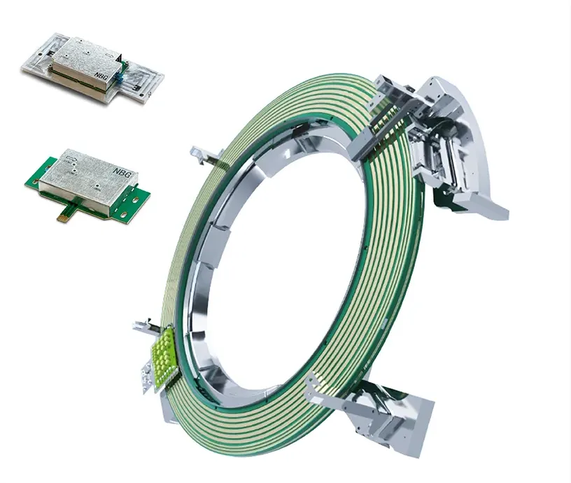
When engineers were making the first CT scanners, they ran into a problem that seemed so simple it's almost funny: you can't spin something forever if it's still connected to lines. That's what a current CT scanner needs to do. It has to rapidly spin its X-ray tube and detector array around a patient while simultaneously moving huge amounts of image data off the spinning frame.
Three needs come together at the same time: high-bandwidth data transfer, constant rotation of 360°, and scanning cycles that last less than a second. With the CT slip ring, you can solve all three at the same time. This guide explains what it is, how it works, the performance standards it must meet, and why it's important for almost all imaging modes used in clinical practice today.
What Is a CT Slip Ring?
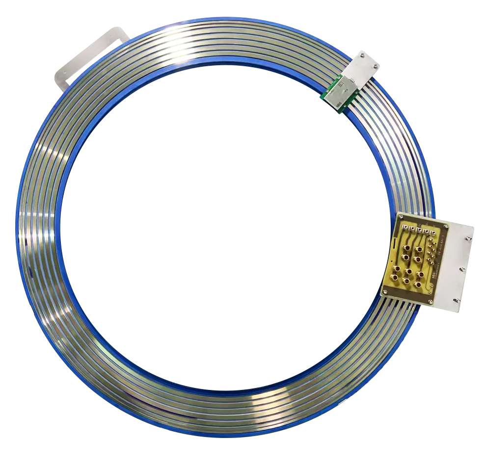
CT slip ring is explained below in terms of its definition and placement.
Definition
A CT slip ring is an electromechanical part for rotary motion. The fixed gantry support on the outside of the CT scanner and the rotating gantry assembly on the inside are always moving relative to each other. Its job is to constantly send electrical power, control signals, and high-speed imaging data between them.
Where it sits in the gantry
The slip ring sits between the frames that are not moving and those that are. The spinning side has the X-ray tube, its high-voltage tank, the detector array, and the data collection system (DAS). The structural support frame and the image reconstruction computer are on the side that stays in place. No matter how fast or how long the gantry spins, power and data must be able to pass between these two sides without problems.
The slip ring is made up of large, concentric conductive rings. The inside diameters of these rings are usually around one meter, but they can be much bigger in wide-bore or research systems. To send power and low-speed messages, stationary brushes press against these moving tracks. But high-speed imaging data goes through special non-contact channels, like capacitive or optical ones, because the amounts of data are too big for brushes to handle safely.
Why Does a CT Scanner Need a Slip Ring?
A CT scanner needs a slip ring for a couple of reasons, and these comprise the following:
The limitation of cabled systems
CT systems used wires before slip rings became the norm. The gantry had to stop and turn around every slice because those cables could only go so far in one direction before they had to unwind. This "step-and-shoot" method caused delays between acquisitions, put stress on the cables, and made it hard to get clear images of moving anatomy. Longer scan times caused more motion artefacts, more breath holds for the patient, and less work getting done in the department.
What does a slip ring enable?
Slip rings have replaced cabled devices, which is the only way that continuous rotation is possible. Since the gantry could keep spinning, the table could move the patient smoothly through the bore while it kept turning. This created the helical or spiral acquisition pattern that became standard in the early 1990s.
Many people say that change was one of the most important hardware advances in CT history. It became common to scan the whole body in one breath-hold; it became possible to do heart imaging, and the idea of volumetric CT stopped being just an idea.
How Does a CT Slip Ring Work?
The working mechanism of a CT slip ring comprises the following stages, which are discussed in the section below.
Power transmission (contacting)
The X-ray tube and the high-voltage electronics that go with it need several kilowatts of power all the time. This power is supplied across the slip ring using sliding brush-on-ring contacts. These are the simplest parts of the system, but they still need to be made of the right material. The contact pair needs to keep its low resistance while rotating and not wear out after millions of cycles. It also needs to do this without making any electrical noise that could mess up picture signals.
Signal transmission
Control and feedback signals, such as gantry timing, status reporting, and positional data, travel across specialised low-frequency tracks. These signals can be sent as separate channels or mixed with other signals. These don't need the imaging data channels' bandwidth, so contact methods are enough here.
Data transmission (contactless)
This is where the engineering gets tougher. Modern multi-row detector arrays easily produce data-rate above 1 Gbps, and wide-area detection systems make that number even higher. When that much data needs to be sent, contacting rings can't keep up, so CT slip rings use non-contact ways for the data channels:
Using electric field modulation, capacitive coupling sends data across a small air gap. It can hit Gigabit-class speeds, keeps its bit error rate very low, and can handle the electromagnetic environment inside a spinning gantry pretty well.Up to 120 Gbps can be reached with multiple parallel channels running at the same time.
Optical data lines use E-optical transducers, laser diodes, and photodiodes to send data as light. These are used when the highest aggregate rates are needed. Up to 20 Gbps can be reached with multiple parallel optical channels running at the same time.
Both methods don't need much upkeep, which is important for systems that handle constant clinical tasks.
Key Performance Requirements of CT Slip Rings
As an example, the numbers below show what most modern clinical CT devices need to work. They are meaningfully different depending on the manufacturer, scanner generation, and detector configuration. Because of this, OEM documentation should always be checked against specific numbers before they are used in a technical specification.
Representative specification table
Parameter | Typical Requirement |
Rotation speed | 120–300 RPM |
Aggregate data rate | 20 Gbps and higher |
Data channel method | Optical or capacitive (contactless) |
Bit error rate (BER) | Better than 10⁻¹² |
Power transfer | Several kW across sliding contacts |
Service life | Maintenance-light to maintenance-free (contactless data) |
Why does each parameter matter?
The rotation speed sets the scan time per revolution. When the gantry rotates faster, the temporal precision is higher, which is very important for cardiac CT because the heart is moving.
The data rate and bit error rate work together to tell the reconstruction computer if it gets a clean, full dataset for each turn. When the BER is higher, artefacts are added to the reconstructed image. This can lead to missed diagnoses or the need for a second scan. Power stability at the slip ring contact has a direct effect on the consistency of the X-ray tube output, which in turn affects image noise and dose.
CT Slip Ring Applications
Some of the applications of CT slip rings are discussed as follows:
By detector configuration
Most hospital imaging departments use 16-row, 64-row, or 128-row CT systems because they are the most powerful. As the number of detector rows goes up, more raw data is produced per rotation. This makes the non-contact data channels work harder to meet the increased demand for bandwidth.
Wide-area detector systems, which are sometimes called "volume CT" (one famous example uses 320 detector rows to cover 16 cm of anatomy per rotation), raise the total data rate to a point where optical lines are almost required. Dual-source systems, which have two sets of tube-detector pairs that are spaced about 90 degrees apart, make the slip ring's channel design even more complicated.
By imaging mode (enabled by continuous rotation)
Helical CT is the standard. It uses a slip ring to move the table continuously through a moving gantry. Cardiac CT and CT angiography depend on rotation times of less than one second to stop the heart from beating.
CT perfusion records changes in contrast over time by taking multiple pictures of the same body part. 4D CT, which is used to plan radiotherapy and see how the lungs move, needs long, constant acquisitions. CT fluoroscopy guides interventional procedures with reconstruction that happens almost in real time. Without continuous rotary power and data transfer, none of these modes could be used in a clinical setting.
Reliability, Lifespan & Common Failure Modes
Over time, the parts of a slip ring that touch things, like the power and signal brushes, wear out. Ring surfaces can become dirty from brush contact, which raises resistance and electrical noise. When used for long periods, thermal cycling can put stress on both the contact materials and the mechanical housing. The non-contact data channels, on the other hand, break down much more slowly and usually don't need any repair during regular service intervals.
Signal integrity slowly decreases due to worn contacts, noise spikes that show up as image artifacts appear from time to time, and, in the worst cases, all contacts fail on one or more channels. To minimize service artifacts, the main things that need to be done are regular inspection, choosing the right materials for the clinical task, and keeping the area around the ring tracks clean.
When OEMs choose a slip ring, the most important specs are the bore diameter, the number of power and data channels, the data-rate headroom compared to the detector configuration, the BER under real-world conditions, and the slip ring's track record of reliability in medical-grade settings.
FAQs
How long does a CT slip ring last?
Service life depends heavily on scan volume and duty cycle. The contacting power and signal tracks accumulate wear proportional to use. Non-contact data channels are largely wear-free and typically outlast the contacting components by a significant margin.
What causes CT slip ring failure?
What makes a big difference in the service life is the job cycle and scan volume. The power and data tracks that touch get worn down over time.
How do you choose a CT slip ring supplier?
Some important things to look at when choosing a CT slip ring are its bore size to fit the gantry, the number of channels it has, its aggregate data bandwidth compared to the detector row configuration, its proven BER under load, and the manufacturer's history of using the device in medical settings.
Contacting vs contactless — what's the difference?
Physical brush-on-ring interfaces are used for contacting channels. They work well with power and low-bandwidth signals, but they wear out over time. Capacitive or optical non-contact channels carry high-speed imaging data across an air gap with almost no wear and tear on the parts and no need for upkeep.
NBG Innovations Group Pte.Ltd.
#13-13A, International Plaza, 10 Anson Road, Singapore (079903)


Navigation
 HomeSustainable
Product